Nissan Pathfinder (2012 year). Instruction — part 44
AV-170
< DTC/CIRCUIT DIAGNOSIS >
[BOSE AUDIO WITHOUT NAVIGATION]
POWER SUPPLY AND GROUND CIRCUIT
1. Turn ignition switch OFF.
2. Disconnect the video monitor connector B76 and the DVD
player connector M205.
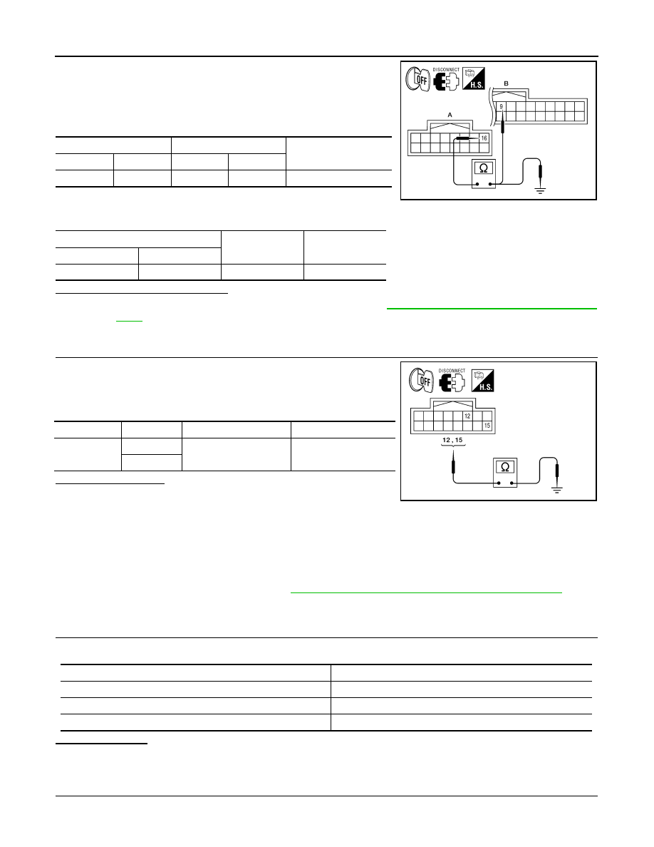
3. Check continuity between the video monitor harness connector
B76 (A) and the DVD player connector M205 (B).
4. Check continuity between video monitor harness connector B76
(A) and ground.
Are continuity results as specified?
YES
>> Check DVD player power and ground supply. Refer to
AV-168, "DVD PLAYER : Diagnosis Proce-
.
NO
>> Repair harness or connector.
3.
CHECK GROUND CIRCUIT
1. Turn ignition switch OFF.
2. Disconnect video monitor connector.
3. Check continuity between video monitor harness connector B76
and ground.
Does continuity exist?
YES
>> Inspection End.
NO
>> Repair harness or connector.
BLUETOOTH CONTROL UNIT
BLUETOOTH CONTROL UNIT : Diagnosis Procedure
INFOID:0000000007347737
Regarding Wiring Diagram information, refer to
AV-225, "Wiring Diagram - Without Navigation System"
1.
CHECK FUSE
Check that the following fuses of the Bluetooth control unit are not blown.
Are the fuses OK?
YES
>> GO TO 2
NO
>> Be sure to eliminate cause of malfunction before installing new fuse.
2.
CHECK POWER SUPPLY CIRCUIT
A
B
Continuity
Connector
Terminal
Connector
Terminal
B76
16
M205
9
Yes
A
—
Continuity
Connector
Terminal
B76
16
Ground
No
ALNIA0517GB
Connector
Terminal
—
Continuity
B76
12
Ground
Yes
15
ALNIA0518GB
Power source
Fuse No.
Battery
29
Ignition switch ACC or ON
4
Ignition switch ON or START
12
August 2012
2012 Pathfinder
AV
POWER SUPPLY AND GROUND CIRCUIT
AV-171
< DTC/CIRCUIT DIAGNOSIS >
[BOSE AUDIO WITHOUT NAVIGATION]
C
D
E
F
G
H
I
J
K
L
M
B
A
O
P
Check voltage between Bluetooth control unit harness connector
and ground.
Are the voltage results as specified?
YES
>> GO TO 3
NO
>> Check harness between Bluetooth control unit and fuse.
3.
CHECK GROUND CIRCUIT
1. Turn ignition switch OFF.
2. Disconnect Bluetooth control unit connector B124.
3. Check continuity between Bluetooth control unit harness con-
nector and ground.
Does continuity exist?
YES
>> Inspection End.
NO
>> Repair harness or connector.
MICROPHONE
MICROPHONE : Diagnosis Procedure
INFOID:0000000007347738
Regarding Wiring Diagram information, refer to
AV-225, "Wiring Diagram - Without Navigation System"
1.
CHECK POWER SUPPLY CIRCUIT (MICROPHONE SIDE)
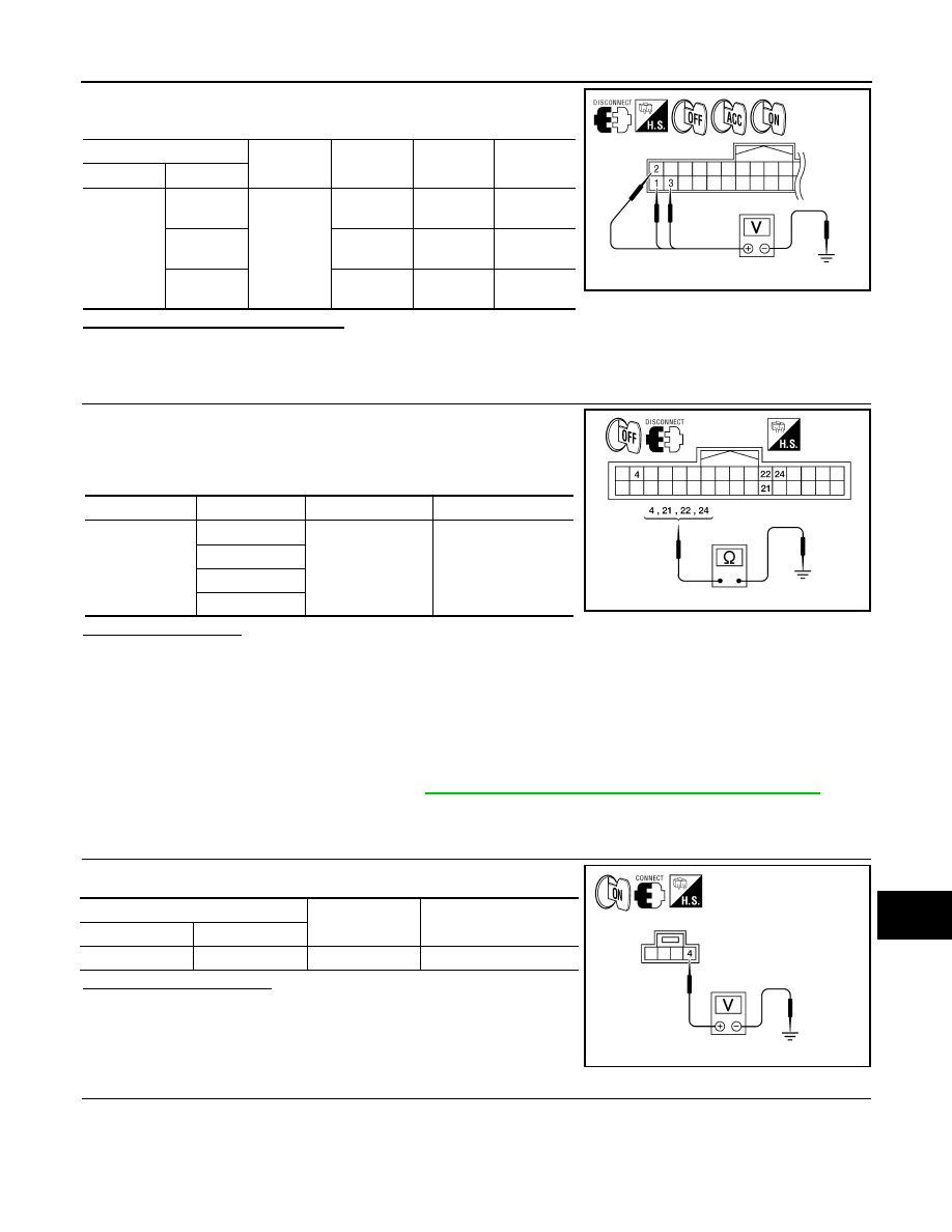
Check voltage between microphone harness connector and ground.
Is proper voltage present?
YES
>> GO TO 4
NO
>> GO TO 2
2.
CHECK POWER SUPPLY CIRCUIT (CONTINUITY)
(+)
(-)
OFF
ACC
ON
Connector
Terminal
B124
1
Ground
Battery
voltage
Battery
voltage
Battery
voltage
2
0V
Battery
voltage
Battery
voltage
3
0V
0V
Battery
voltage
WKIA4389E
Connector
Terminal
—
Continuity
B124
4
Ground
Yes
21
22
24
AWLIA1681ZZ
(+)
(-)
Value (Approx.)
Connector
Terminal
R8
4
Ground
5V
WKIA5796E
August 2012
2012 Pathfinder
AV-172
< DTC/CIRCUIT DIAGNOSIS >
[BOSE AUDIO WITHOUT NAVIGATION]
POWER SUPPLY AND GROUND CIRCUIT
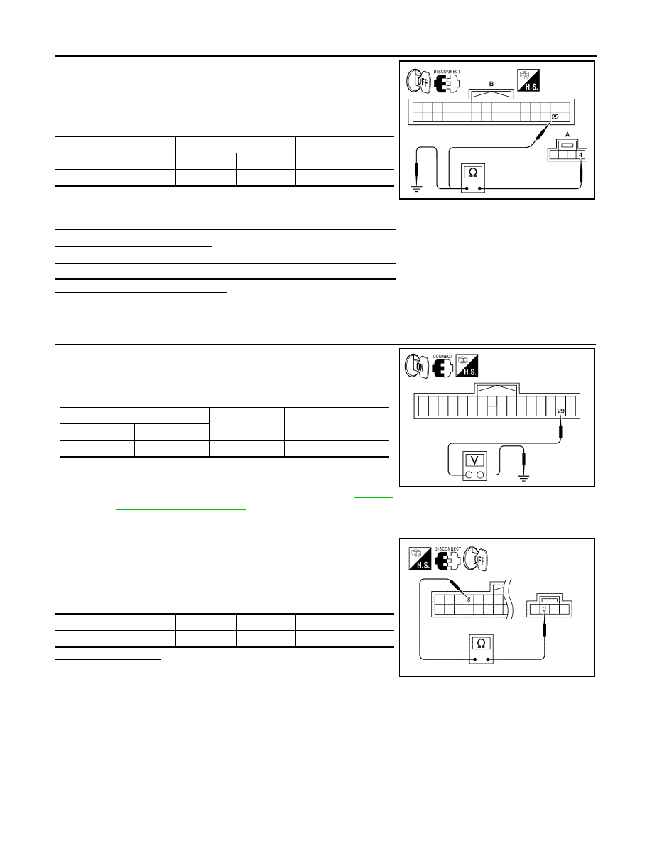
1. Turn ignition switch OFF.
2. Disconnect Bluetooth control unit and microphone connectors.
3. Check continuity between microphone harness connector R8
(A) terminal 4 and Bluetooth control unit harness connector
B124 (B) terminal 29.
4. Check continuity between microphone harness connector R8
(A) terminal 4 and ground.
Are continuity results as specified?
YES
>> GO TO 3
NO
>> Repair harness or connector.
3.
CHECK POWER SUPPLY CIRCUIT (BLUETOOTH CONTROL UNIT SIDE)
1. Connect Bluetooth control unit connector.
2. Turn ignition switch ON.
3. Check voltage between Bluetooth control unit harness connec-
tor and ground.
Is proper voltage present?
YES
>> Inspection End.
NO
>> Replace Bluetooth control unit. Refer to
.
4.
CHECK GROUND CIRCUIT
1. Turn ignition switch OFF.
2. Disconnect Bluetooth control unit and microphone connectors.
3. Check continuity between microphone harness connector R8
terminal 2 and Bluetooth control unit harness connector B124
terminal 8.
Is continuity present?
YES
>> Inspection End.
NO
>> Repair harness or connector.
A
B
Continuity
Connector
Terminal
Connector
Terminal
R8
4
B124
29
Yes
A
—
Continuity
Connector
Terminal
R8
4
Ground
No
ALNIA0132ZZ
(+)
(-)
Value (Approx.)
Connector
Terminal
B124
29
Ground
5V
ALNIA0133ZZ
Connector
Terminal
Connector
Terminal
Continuity
R8
2
B124
8
Yes
ALNIA0170ZZ
August 2012
2012 Pathfinder
AV
RGB (R: RED) SIGNAL CIRCUIT
AV-173
< DTC/CIRCUIT DIAGNOSIS >
[BOSE AUDIO WITHOUT NAVIGATION]
C
D
E
F
G
H
I
J
K
L
M
B
A
O
P
RGB (R: RED) SIGNAL CIRCUIT
Description
INFOID:0000000007347739
Transmit the image displayed with AV control unit with RGB signal to the display unit.
Diagnosis Procedure
INFOID:0000000007347740
Regarding Wiring Diagram information, refer to
AV-225, "Wiring Diagram - Without Navigation System"
1.
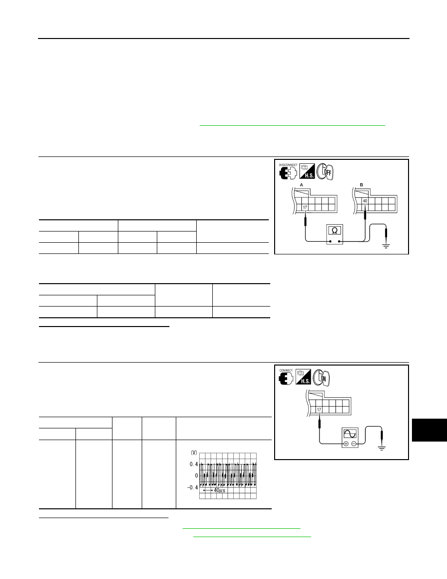
CHECK CONTINUITY RGB (R: RED) SIGNAL CIRCUIT
1. Turn ignition switch OFF.
2. Disconnect display unit connector M93 and AV control unit con-
nector M45.
3. Check continuity between display unit harness connector M93
(A) terminal 17 and AV control unit harness connector M45 (B)
terminal 40.
4. Check continuity between display unit harness connector M93
(A) terminal 17 and ground.
Are the continuity results as specified?
YES
>> GO TO 2
NO
>> Repair harness or connector.
2.
CHECK RGB (R: RED) SIGNAL
1. Connect display unit connector M93 and AV control unit connec-
tor M45.
2. Turn ignition switch ON.
3. Check signal between display unit harness connector M93 ter-
minal 17 and ground.
Are the voltage readings as specified?
YES
>> Replace display unit. Refer to
AV-257, "Removal and Installation"
NO
>> Replace AV control unit. Refer to
AV-255, "Removal and Installation"
.
A
B
Continuity
Connector
Terminal
Connector
Terminal
M93
17
M45
40
Yes
A
—
Continuity
Connector
Terminal
M93
17
Ground
No
ALNIA0382GB
(+)
(-)
Condition
Reference signal
Connector
Terminal
M93
17
Ground
Receive
audio sig-
nal
ALNIA0383GB
SKIB2238J
August 2012
2012 Pathfinder
AV-174
< DTC/CIRCUIT DIAGNOSIS >
[BOSE AUDIO WITHOUT NAVIGATION]
RGB (G: GREEN) SIGNAL CIRCUIT
RGB (G: GREEN) SIGNAL CIRCUIT
Description
INFOID:0000000007347741
Transmit the image displayed with AV control unit with RGB signal to the display unit.
Diagnosis Procedure
INFOID:0000000007347742
Regarding Wiring Diagram information, refer to
AV-225, "Wiring Diagram - Without Navigation System"
1.
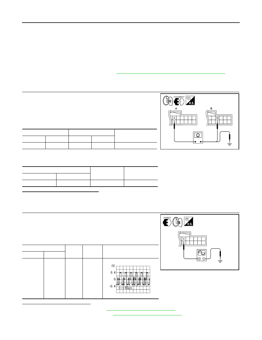
CHECK CONTINUITY RGB (G: GREEN) SIGNAL CIRCUIT
1. Turn ignition switch OFF.
2. Disconnect display unit connector M93 and AV control unit con-
nector M45.
3. Check continuity between display unit harness connector M93
(A) terminal 6 and AV control unit harness connector M45 (B)
terminal 39.
4. Check continuity between display unit harness connector M93
(A) terminal 6 and ground.
Are the continuity results as specified?
YES
>> GO TO 2
NO
>> Repair harness or connector.
2.
CHECK RGB (G: GREEN) SIGNAL
1. Connect display unit connector M93 and AV control unit connec-
tor M45.
2. Turn ignition switch ON.
3. Check signal between display unit harness connector M93 ter-
minal 6 and ground.
Are voltage readings as specified?
YES
>> Replace display unit. Refer to
AV-257, "Removal and Installation"
NO
>> Replace AV control unit. Refer to
AV-255, "Removal and Installation"
.
A
B
Continuity
Connector
Terminal
Connector
Terminal
M93
6
M45
39
Yes
A
—
Continuity
Connector
Terminal
M93
6
Ground
No
ALNIA0384GB
(+)
(-)
Condition
Reference signal
Connector
Terminal
M93
6
Ground
Receive
audio sig-
nal
ALNIA0385GB
SKIB2236J
August 2012
2012 Pathfinder
AV
RGB (B: BLUE) SIGNAL CIRCUIT
AV-175
< DTC/CIRCUIT DIAGNOSIS >
[BOSE AUDIO WITHOUT NAVIGATION]
C
D
E
F
G
H
I
J
K
L
M
B
A
O
P
RGB (B: BLUE) SIGNAL CIRCUIT
Description
INFOID:0000000007347743
Transmit the image displayed with AV control unit with RGB signal to the display unit.
Diagnosis Procedure
INFOID:0000000007347744
Regarding Wiring Diagram information, refer to
AV-225, "Wiring Diagram - Without Navigation System"
1.
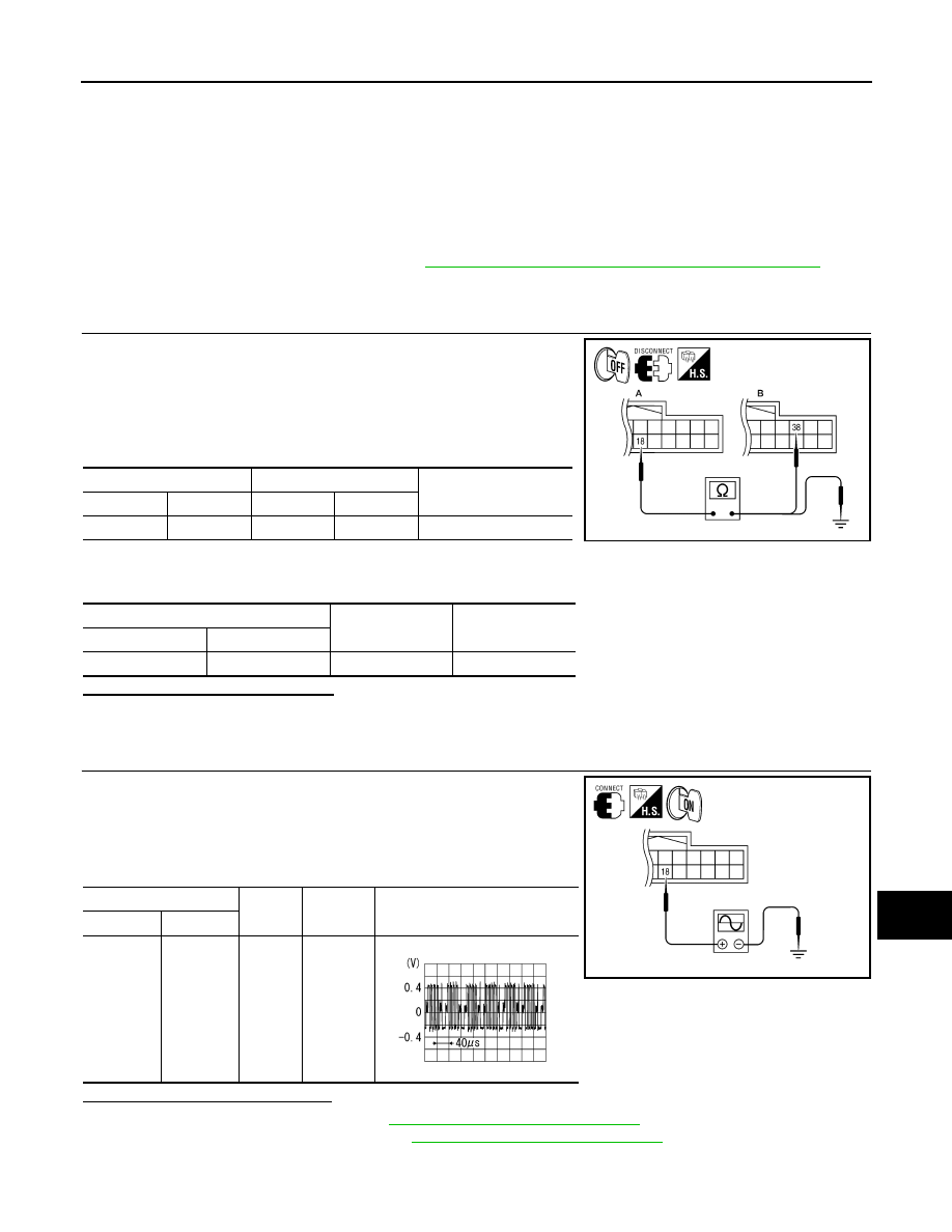
CHECK CONTINUITY RGB (B: BLUE) SIGNAL CIRCUIT
1. Turn ignition switch OFF.
2. Disconnect display unit connector M93 and AV control unit con-
nector M45.
3. Check continuity between display unit harness connector M93
(A) terminal 18 and AV control unit harness connector M45 (B)
terminal 38.
4. Check continuity between display unit harness connector M93
(A) terminal 18 and ground.
Are continuity results as specified?
YES
>> GO TO 2
NO
>> Repair harness or connector.
2.
CHECK RGB (B: BLUE) SIGNAL
1. Connect display unit connector M93 and AV control unit connec-
tor M45.
2. Turn ignition switch ON.
3. Check signal between display unit harness connector M93 ter-
minal 18 and ground.
Are voltage readings as specified?
YES
>> Replace display unit. Refer to
AV-257, "Removal and Installation"
NO
>> Replace AV control unit. Refer to
AV-255, "Removal and Installation"
.
A
B
Continuity
Connector
Terminal
Connector
Terminal
M93
18
M45
38
Yes
A
—
Continuity
Connector
Terminal
M93
18
Ground
No
ALNIA0386GB
(+)
(-)
Condition
Reference signal
Connector
Terminal
M93
18
Ground
Receive
audio sig-
nal
ALNIA0387GB
SKIB2237J
August 2012
2012 Pathfinder
AV-176
< DTC/CIRCUIT DIAGNOSIS >
[BOSE AUDIO WITHOUT NAVIGATION]
RGB SYNCHRONIZING SIGNAL CIRCUIT
RGB SYNCHRONIZING SIGNAL CIRCUIT
Description
INFOID:0000000007347745
Transmit the RGB synchronizing signal to the display unit so as to synchronize the RGB image displayed with
AV control unit.
Diagnosis Procedure
INFOID:0000000007347746
Regarding Wiring Diagram information, refer to
AV-225, "Wiring Diagram - Without Navigation System"
1.
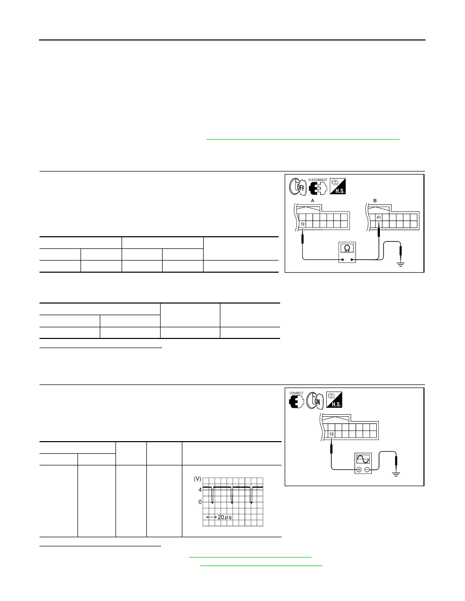
CHECK CONTINUITY RGB SYNCHRONIZING SIGNAL CIRCUIT
1. Turn ignition switch OFF.
2. Disconnect display unit connector M93 and AV control unit con-
nector M45.
3. Check continuity between display unit harness connector M93
(A) terminal 19 and AV control unit harness connector M45 (B)
terminal 41.
4. Check continuity between display unit harness connector M93
(A) terminal 19 and ground.
Are continuity results as specified?
YES
>> GO TO 2
NO
>> Repair harness or connector.
2.
CHECK RGB SYNCHRONIZING SIGNAL
1. Connect display unit connector M93 and AV control unit connec-
tor M45.
2. Turn ignition switch ON.
3. Check signal between display unit harness connector M93 ter-
minal 19 and ground.
Are voltage readings as specified?
YES
>> Replace display unit. Refer to
AV-257, "Removal and Installation"
NO
>> Replace AV control unit. Refer to
AV-255, "Removal and Installation"
.
A
B
Continuity
Connector
Terminal
Connector
Terminal
M93
19
M45
41
Yes
A
—
Continuity
Connector
Terminal
M93
19
Ground
No
ALNIA0388GB
(+)
(-)
Condition
Reference signal
Connector
Terminal
M93
19
Ground
Receive
audio sig-
nal
ALNIA0389GB
SKIB3603E
August 2012
2012 Pathfinder
AV
RGB AREA (YS) SIGNAL CIRCUIT
AV-177
< DTC/CIRCUIT DIAGNOSIS >
[BOSE AUDIO WITHOUT NAVIGATION]
C
D
E
F
G
H
I
J
K
L
M
B
A
O
P
RGB AREA (YS) SIGNAL CIRCUIT
Description
INFOID:0000000007347747
Transmits the display area of RGB image displayed by AV control unit with RGB area (YS) signal to display
unit.
Diagnosis Procedure
INFOID:0000000007347748
Regarding Wiring Diagram information, refer to
AV-225, "Wiring Diagram - Without Navigation System"
1.
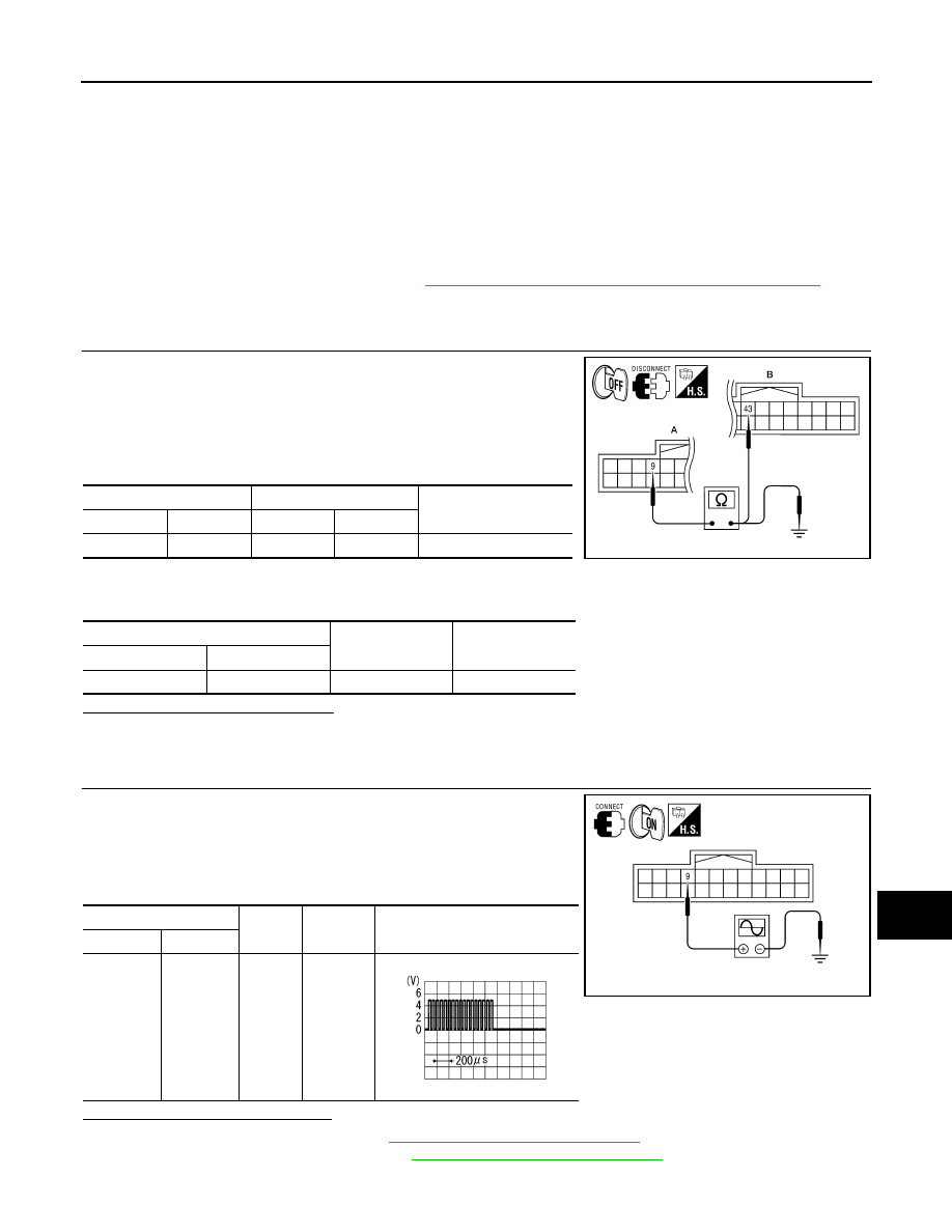
CHECK CONTINUITY RGB AREA (YS) SIGNAL CIRCUIT
1. Turn ignition switch OFF.
2. Disconnect display unit connector M93 and AV control unit con-
nector M45.
3. Check continuity between display unit harness connector M93
(A) terminal 9 and AV control unit harness connector M45 (B)
terminal 43.
4. Check continuity between display unit harness connector M93
(A) terminal 9 and ground.
Are continuity results as specified?
YES
>> GO TO 2
NO
>> Repair harness or connector.
2.
CHECK RGB SYNCHRONIZING SIGNAL
1. Connect display unit connector M93 and AV control unit connec-
tor M45.
2. Turn ignition switch ON.
3. Check signal between display unit harness connector M93 ter-
minal 9 and ground.
Are voltage readings as specified?
YES
>> Replace display unit. Refer to
AV-257, "Removal and Installation"
NO
>> Replace AV control unit. Refer to
AV-255, "Removal and Installation"
.
A
B
Continuity
Connector
Terminal
Connector
Terminal
M93
9
M45
43
Yes
A
—
Continuity
Connector
Terminal
M93
9
Ground
No
ALNIA0390GB
(+)
(-)
Condition
Reference signal
Connector
Terminal
M93
9
Ground
Receive
audio sig-
nal
ALNIA0391GB
PKIB4948J
August 2012
2012 Pathfinder
Нет комментариевНе стесняйтесь поделиться с нами вашим ценным мнением.
Текст