Nissan Pathfinder (2012 year). Instruction — part 43
AV-162
< DTC/CIRCUIT DIAGNOSIS >
[BOSE AUDIO WITHOUT NAVIGATION]
POWER SUPPLY AND GROUND CIRCUIT
POWER SUPPLY AND GROUND CIRCUIT
AV CONTROL UNIT
AV CONTROL UNIT : Diagnosis Procedure
INFOID:0000000007347728
Regarding Wiring Diagram information, refer to
AV-225, "Wiring Diagram - Without Navigation System"
1.
CHECK FUSES
Check that the following fuses of the AV control unit are not are not blown.
Are the fuses OK?
YES
>> GO TO 2
NO
>> If fuse is blown, be sure to eliminate cause of malfunction before installing new fuse.
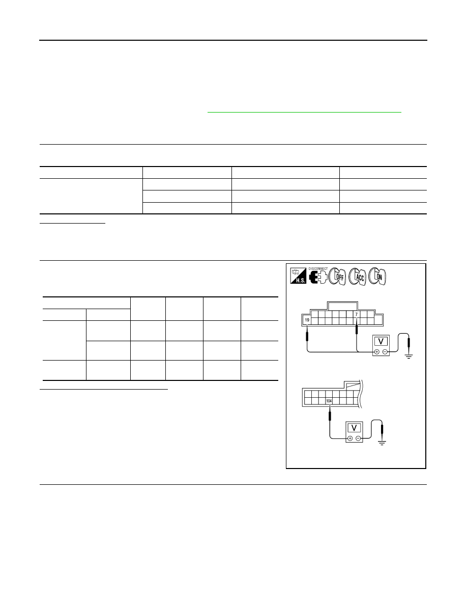
2.
POWER SUPPLY CIRCUIT CHECK
1. Disconnect AV control unit connectors M42 and M70.
2. Check voltage between the AV control unit connectors M42 and
M70 and ground.
Are the voltage results as specified?
YES
>> GO TO 3
NO
>> • Check connector housings for disconnected or loose
terminals.
• Repair harness or connector.
3.
GROUND CIRCUIT CHECK
1. Turn ignition switch OFF.
2. Check continuity between AV control unit harness connectors M42, M45, M46, M70 and ground.
Unit
Terminals
Signal name
Fuse No.
AV control unit
19
Battery power
29
7
Ignition switch ACC or ON
4
104
Ignition switch ON or START
12
(+)
(-)
OFF
ACC
ON
Connector
Terminal
M42
7
Ground
0V
Battery
voltage
Battery
voltage
19
Ground
Battery
voltage
Battery
voltage
Battery
voltage
M70
104
Ground
0V
0V
Battery
voltage
AWNIA0456ZZ
August 2012
2012 Pathfinder
AV
POWER SUPPLY AND GROUND CIRCUIT
AV-163
< DTC/CIRCUIT DIAGNOSIS >
[BOSE AUDIO WITHOUT NAVIGATION]
C
D
E
F
G
H
I
J
K
L
M
B
A
O
P
Are the continuity results as specified?
YES
>> Inspection End.
NO
>> Repair AV control unit ground.
DISPLAY UNIT
DISPLAY UNIT : Diagnosis Procedure
INFOID:0000000007347729
Regarding Wiring Diagram information, refer to
AV-225, "Wiring Diagram - Without Navigation System"
1.
CHECK POWER SUPPLY CIRCUIT
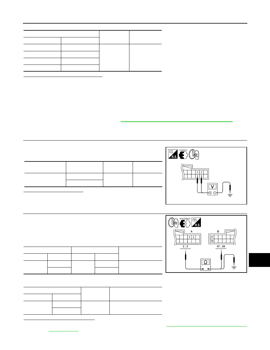
1. Turn ignition switch to ACC.
2. Check voltage between display unit harness connector M93 and
ground.
Does specified voltage exist?
YES
>> GO TO 3
NO
>> GO TO 2
2.
CHECK POWER SUPPLY CIRCUIT
1. Turn ignition switch OFF.
2. Disconnect the display unit connector M93 and the AV control
unit connector M45.
3. Check continuity between the display unit harness connector
M93 (A) and the AV control unit connector M45 (B).
4. Check continuity between the display unit harness connector M93 (A) and ground.
Are continuity results as specified?
YES
>> Check AV control unit power and ground supply. Refer to
AV-162, "AV CONTROL UNIT : Diagno-
NO
>> Repair harness or connector.
(+)
(-)
Continuity
Connector
Terminal
M42
20
Ground
Yes
M45
54
M46
68
M70
85
Connector
Terminal
Ignition switch
position
Value (Approx.)
M93
2
ACC
9V
3
ALNIA0317GB
A
B
Continuity
Connector
Terminal
Connector
Terminal
M93
2
M45
59
Yes
3
47
A
—
Continuity
Connector
Terminal
M93
2
Ground
No
3
ALNIA0318GB
August 2012
2012 Pathfinder

AV-164
< DTC/CIRCUIT DIAGNOSIS >
[BOSE AUDIO WITHOUT NAVIGATION]
POWER SUPPLY AND GROUND CIRCUIT
3.
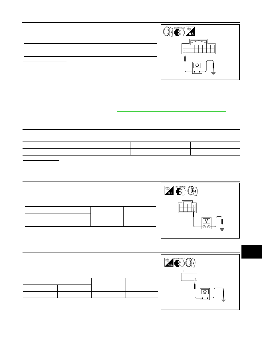
CHECK GROUND CIRCUIT
1. Turn ignition switch OFF.
2. Disconnect display unit connector.
3. Check continuity between display unit harness connector and
ground.
Does continuity exist?
YES
>> Inspection End.
NO
>> Repair harness or connector.
A/C AND AV SWITCH ASSEMBLY
A/C AND AV SWITCH ASSEMBLY : Diagnosis Procedure
INFOID:0000000007347730
Regarding Wiring Diagram information, refer to
AV-225, "Wiring Diagram - Without Navigation System"
1.
CHECK FUSE
Check that the fuse of the AC and AV switch assembly is not blown.
Is the fuse OK?
YES
>> GO TO 2
NO
>> If fuse is blown, be sure to eliminate cause of malfunction before installing new fuse.
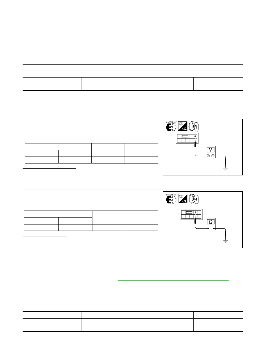
2.
POWER SUPPLY CIRCUIT CHECK
1. Disconnect A/C and AV switch assembly connector M98.
2. Check voltage between the A/C and AV switch assembly con-
nector M98 and ground.
Are the voltage results as specified?
YES
>> GO TO 3
NO
>> • Check connector housings for disconnected or loose
terminals.
• Repair harness or connector.
3.
GROUND CIRCUIT CHECK
Connector
Terminal
—
Continuity
M93
1
Ground
Yes
ALNIA0319GB
Unit
Terminal
Signal name
Fuse No.
A/C and AV switch assembly
2
Ignition switch ACC or ON
4
(+)
(-)
OFF
ACC
ON
Connector
Terminal
M98
2
Ground
0V
Battery
voltage
Battery
voltage
ALNIA0315GB
August 2012
2012 Pathfinder
AV
POWER SUPPLY AND GROUND CIRCUIT
AV-165
< DTC/CIRCUIT DIAGNOSIS >
[BOSE AUDIO WITHOUT NAVIGATION]
C
D
E
F
G
H
I
J
K
L
M
B
A
O
P
1. Turn ignition switch OFF.
2. Check continuity between A/C and AV switch assembly harness
connector M98 and ground.
Does continuity exist?
YES
>> Inspection End.
NO
>> Repair harness or ground.
BOSE SPEAKER AMP
BOSE SPEAKER AMP : Diagnosis Procedure
INFOID:0000000007347731
Regarding Wiring Diagram information, refer to
AV-225, "Wiring Diagram - Without Navigation System"
1.
CHECK FUSE
Check that the BOSE speaker amp. fuse is not blown.
Are the fuses OK?
YES
>> GO TO 2
NO
>> Be sure to eliminate cause of malfunction before installing new fuse.
2.
CHECK POWER SUPPLY CIRCUIT
1. Turn ignition switch OFF.
2. Disconnect BOSE speaker amp. connector.
3. Check voltage between BOSE speaker amp. harness connector
B74 terminal 1 and ground.
Is battery voltage present?
YES
>> GO TO 3
NO
>> Check harness between BOSE speaker amp. and fuse.
3.
CHECK GROUND CIRCUIT
1. Turn ignition switch OFF.
2. Disconnect BOSE speaker amp. connector.
3. Check continuity between BOSE speaker amp. harness connec-
tor B74 terminal 17 and ground.
Does continuity exist?
YES
>> Inspection End.
NO
>> Repair harness or connector.
SUBWOOFER
Connector
Terminal
—
Continuity
M98
1
Ground
Yes
ALNIA0316GB
Unit
Terminal
Signal name
Fuse No.
BOSE speaker amp.
1
Battery power
29
(+)
(-)
Voltage (approx.)
Connector
Terminal
B74
1
Ground
Battery voltage
ALNIA0527GB
(+)
(-)
Continuity
Connector
Terminal
B74
17
Ground
Yes
ALNIA0526GB
August 2012
2012 Pathfinder
AV-166
< DTC/CIRCUIT DIAGNOSIS >
[BOSE AUDIO WITHOUT NAVIGATION]
POWER SUPPLY AND GROUND CIRCUIT
SUBWOOFER : Diagnosis Procedure
INFOID:0000000007347732
Regarding Wiring Diagram information, refer to
AV-225, "Wiring Diagram - Without Navigation System"
1.
CHECK FUSE
Check that the subwoofer fuse is not blown.
Is the fuse OK?
YES
>> GO TO 2
NO
>> Be sure to eliminate cause of malfunction before installing new fuse.
2.
CHECK POWER SUPPLY CIRCUIT
1. Turn ignition switch OFF.
2. Disconnect subwoofer connector.
3. Check voltage between subwoofer harness connector B72 ter-
minal 6 and ground.
Is battery voltage present?
YES
>> GO TO 3
NO
>> Check harness between subwoofer and fuse.
3.
CHECK GROUND CIRCUIT
1. Turn ignition switch OFF.
2. Check continuity between subwoofer harness connector B72
terminal 5 and ground.
Does continuity exist?
YES
>> Inspection End.
NO
>> Repair harness or connector.
SATELLITE RADIO TUNER
SATELLITE RADIO TUNER : Diagnosis Procedure
INFOID:0000000007347733
Regarding Wiring Diagram information, refer to
AV-225, "Wiring Diagram - Without Navigation System"
1.
CHECK FUSES
Check that the following fuses of the satellite radio tuner (factory installed) are not blown.
Unit
Terminal
Signal name
Fuse No.
Subwoofer
6
Battery power
17
(+)
(-)
Voltage (approx.)
Connector
Terminal
B72
6
Ground
Battery voltage
ALNIA0528GB
(+)
(-)
Continuity
Connector
Terminal
B72
5
Ground
Yes
ALNIA0529GB
Unit
Terminals
Signal name
Fuse No.
Satellite radio tuner (factory in-
stalled)
32
Battery power
17
36
Ignition switch ACC or ON
4
August 2012
2012 Pathfinder
AV
POWER SUPPLY AND GROUND CIRCUIT
AV-167
< DTC/CIRCUIT DIAGNOSIS >
[BOSE AUDIO WITHOUT NAVIGATION]
C
D
E
F
G
H
I
J
K
L
M
B
A
O
P
Are the fuses OK?
YES
>> GO TO 2
NO
>> If fuse is blown, be sure to eliminate cause of malfunction before installing new fuse.
2.
POWER SUPPLY CIRCUIT CHECK
1. Turn ignition switch OFF.
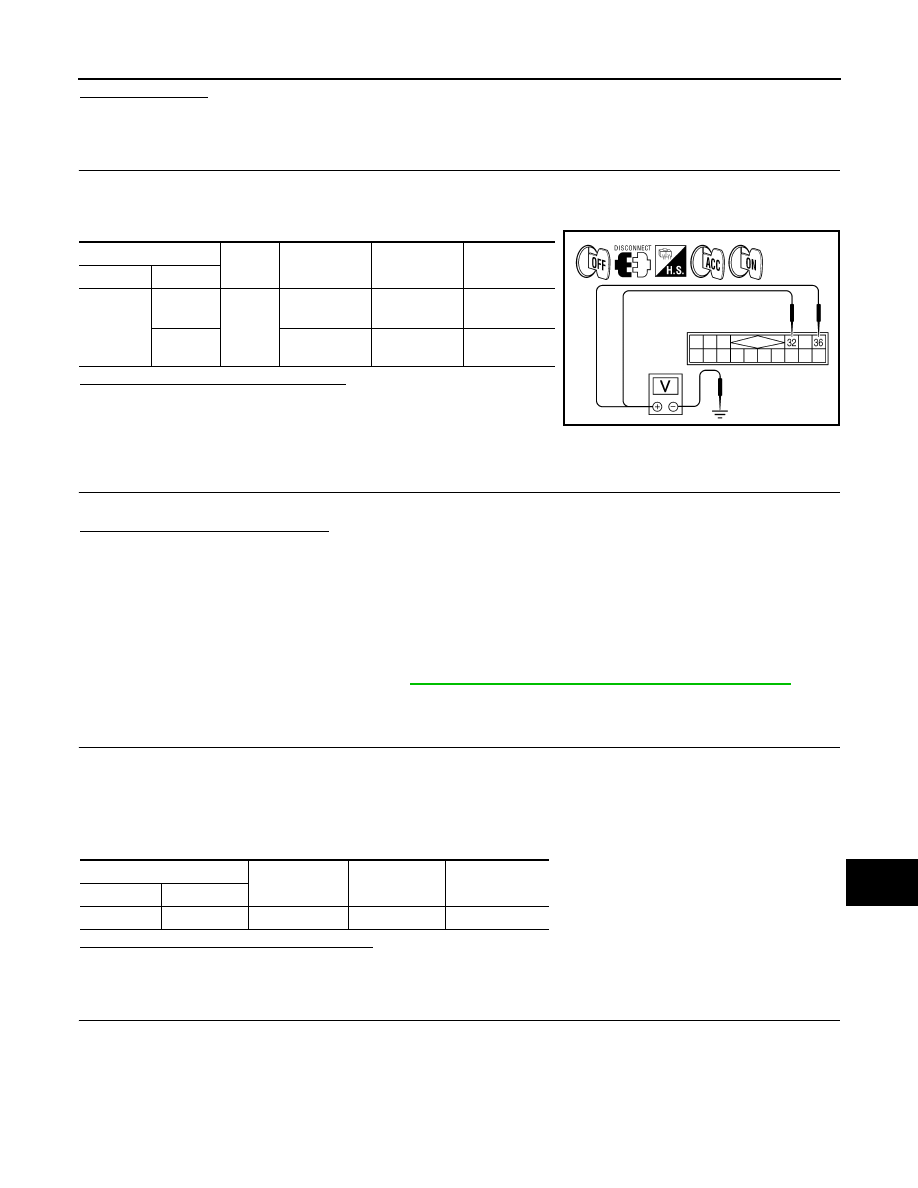
2. Disconnect satellite radio tuner (factory installed) connector M41.
3. Check voltage between the satellite radio tuner (factory installed) and ground.
Are the voltage readings as specified?
YES
>> GO TO 3
NO
>> • Check connector housings for disconnected or loose
terminals.
• Repair harness or connector.
3.
GROUND CIRCUIT CHECK
Inspect satellite radio tuner (factory installed) case ground.
Does case ground pass inspection?
YES
>> Inspection End.
NO
>> Repair satellite radio tuner (factory installed) case ground.
REAR VIEW CAMERA
REAR VIEW CAMERA : Diagnosis Procedure
INFOID:0000000007347734
Regarding Wiring Diagram information, refer to
AV-225, "Wiring Diagram - Without Navigation System"
1.
CHECK POWER SUPPLY CIRCUIT (REAR VIEW CAMERA SIDE)
NOTE:
Apply parking brakes before proceeding.
1. Turn ignition switch ON.
2. Shift transmission into reverse.
3. Check voltage between rear view camera harness connector D551 terminal 2 and ground.
Is voltage reading approximately 12 volts?
YES
>> GO TO 4.
NO
>> GO TO 2.
2.
CHECK POWER SUPPLY CIRCUIT (CONTINUITY)
1. Turn ignition switch OFF.
2. Disconnect rear view camera and AV control unit connectors.
3. Check continuity between rear view camera harness connector D551 terminal 2 and AV control unit har-
ness connector M134 terminal 105.
(+)
(-)
OFF
ACC
ON
Connector
Terminal
M41
32
Ground
Battery volt-
age
Battery volt-
age
Battery volt-
age
36
0V
Battery volt-
age
Battery volt-
age
WKIA4539E
(+)
(-)
Transmission
position
Value (Approx.)
Connector
Terminal
D551
2
Ground
Reverse
12V
August 2012
2012 Pathfinder

AV-168
< DTC/CIRCUIT DIAGNOSIS >
[BOSE AUDIO WITHOUT NAVIGATION]
POWER SUPPLY AND GROUND CIRCUIT
4. Check continuity between rear view camera harness connector D551 terminal 2 and ground.
Are continuity test results as specified?
YES
>> GO TO 3.
NO
>> Repair harness or connector.
3.
CHECK REVERSE POSITION INPUT SIGNAL
1. Turn ignition switch ON.
2. Shift transmission into reverse.
3. Check voltage between AV control unit harness connector M134 terminal 105 and ground.
Is voltage reading approximately 12 volts?
YES
>> Replace AV control unit. Refer to
AV-255, "Removal and Installation"
.
NO
>> Check harness for open or short between AV control unit and back-up lamp relay.
4.
CHECK GROUND CIRCUIT
1. Turn ignition switch OFF.
2. Disconnect rear view camera harness connector.
3. Check continuity between rear view camera harness connector D551 terminal 1 and ground.
Does continuity exist?
YES
>> Inspection End.
NO
>> Repair harness or connector.
DVD PLAYER
DVD PLAYER : Diagnosis Procedure
INFOID:0000000007347735
Regarding Wiring Diagram information, refer to
AV-225, "Wiring Diagram - Without Navigation System"
1.
CHECK FUSE
Check that the following fuses of the DVD player are not blown.
Is the fuse OK?
YES
>> GO TO 2
NO
>> If fuse is blown, be sure to eliminate cause of malfunction before installing new fuse.
2.
POWER SUPPLY CIRCUIT CHECK
Connector
Terminal
Connector
Terminal
Continuity
D551
2
M134
105
Yes
Connector
Terminal
—
Continuity
D551
2
Ground
No
(+)
(-)
Transmission
position
Value (Approx.)
Connector
Terminal
M134
105
Ground
Reverse
12V
Connector
Terminal
—
Continuity
D551
1
Ground
Yes
Unit
Terminal
Signal name
Fuse No.
DVD player
21
Battery power
29
24
Ignition switch ACC or ON
4
August 2012
2012 Pathfinder
AV
POWER SUPPLY AND GROUND CIRCUIT
AV-169
< DTC/CIRCUIT DIAGNOSIS >
[BOSE AUDIO WITHOUT NAVIGATION]
C
D
E
F
G
H
I
J
K
L
M
B
A
O
P
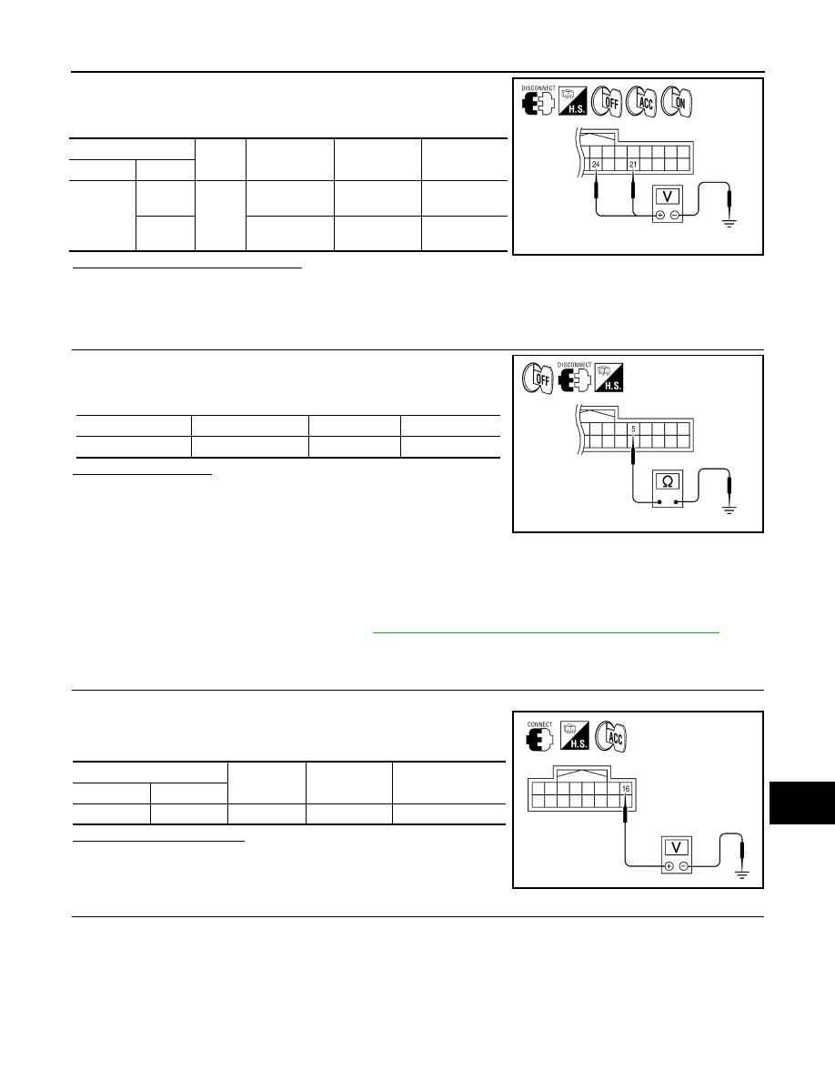
1. Disconnect DVD player connector M205.
2. Check voltage between the DVD player connector M205 and
ground.
Are the voltage results as specified?
YES
>> GO TO 3
NO
>> • Check connector housings for disconnected or loose terminals.
• Repair harness or connector.
3.
GROUND CIRCUIT CHECK
1. Turn ignition switch OFF.
2. Check continuity between DVD player harness connector M205
terminal 5 and ground.
Does continuity exist?
YES
>> Inspection End.
NO
>> Repair DVD player ground.
VIDEO MONITOR
VIDEO MONITOR : Diagnosis Procedure
INFOID:0000000007347736
Regarding Wiring Diagram information, refer to
AV-225, "Wiring Diagram - Without Navigation System"
1.
CHECK POWER SUPPLY CIRCUIT
1. Turn ignition switch to ACC.
2. Check voltage between video monitor harness connector B76
and ground.
Does battery voltage exist?
YES
>> GO TO 3
NO
>> GO TO 2
2.
CHECK POWER SUPPLY CIRCUIT
(+)
(-)
OFF
ACC
ON
Connector
Terminal
M205
21
Ground
Battery voltage Battery voltage
Battery volt-
age
24
0V
Battery voltage
Battery volt-
age
ALNIA0325GB
Connector
Terminal
—
Continuity
M205
5
Ground
Yes
ALNIA0326GB
(+)
(-)
Ignition switch
position
Value (Approx.)
Connector
Terminal
B76
16
Ground
ACC
Battery voltage
ALNIA0516GB
August 2012
2012 Pathfinder
Нет комментариевНе стесняйтесь поделиться с нами вашим ценным мнением.
Текст