Nissan Pathfinder (2012 year). Instruction — part 420
HAC-82
< DTC/CIRCUIT DIAGNOSIS >
[AUTOMATIC AIR CONDITIONER]
IN-VEHICLE SENSOR
IN-VEHICLE SENSOR
Component Description
INFOID:0000000007356388
COMPONENT DESCRIPTION
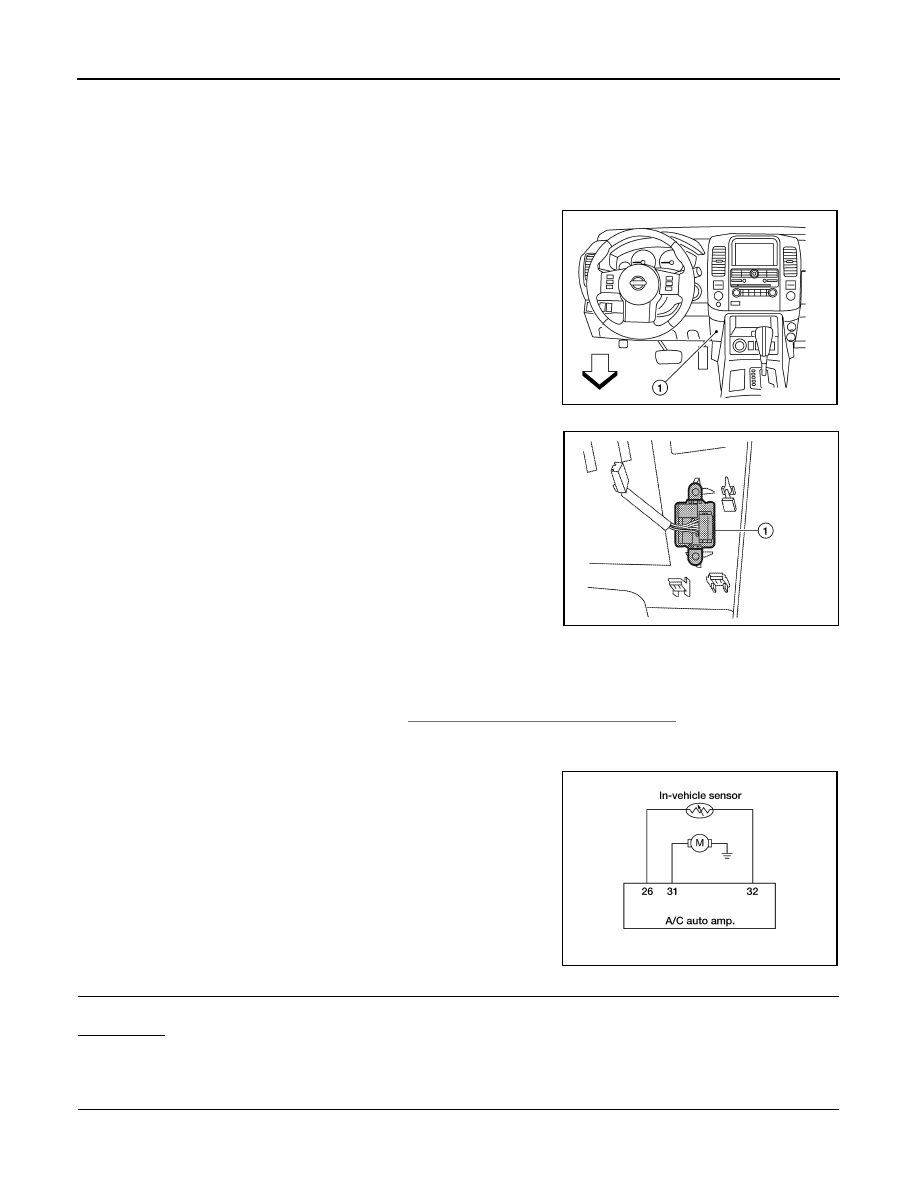
In-vehicle Sensor
The in-vehicle sensor (1) is located on the lower instrument panel
LH. It converts variations in temperature of passenger compartment
air (drawn in through the integrated fan) into a resistance value. It is
then input into the A/C auto amp.
In-Vehicle Sensor Diagnosis Procedure
INFOID:0000000007356389
Regarding Wiring Diagram information, refer to
HAC-95, "Wiring Diagram - Automatic"
DIAGNOSTIC PROCEDURE FOR IN-VEHICLE SENSOR
SYMPTOM: In-vehicle sensor circuit is open or shorted. Using the
CONSULT, DTC B2578 or B2579 is displayed. Without a CONSULT,
code 30, 31, 44 or 46 is indicated on A/C auto amp. as a result of
conducting self-diagnosis.
1.
CHECK IN-VEHICLE SENSOR CIRCUIT
Is self-diagnosis DTC B2578 or B2579 (with CONSULT) or code 30, 31 44 or 46 (without CONSULT) present?
YES or NO?
YES
>> GO TO 6.
NO
>> GO TO 2.
2.
CHECK VOLTAGE BETWEEN IN-VEHICLE SENSOR AND GROUND
AWIIA0264ZZ
AWIIA0265ZZ
AWIIA0166GB
August 2012
2012 Pathfinder
IN-VEHICLE SENSOR
HAC-83
< DTC/CIRCUIT DIAGNOSIS >
[AUTOMATIC AIR CONDITIONER]
C
D
E
F
G
H
J
K
L
M
A
B
HAC
N
O
P
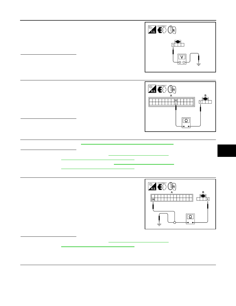
1. Disconnect in-vehicle sensor connector.
2. Turn ignition switch ON.
3. Check voltage between in-vehicle sensor harness connector
M32 terminal 1 and ground.
Is the inspection result normal?
YES
>> GO TO 3.
NO
>> GO TO 5.
3.
CHECK CIRCUIT CONTINUITY BETWEEN IN-VEHICLE SENSOR AND A/C AUTO AMP.
1. Turn ignition switch OFF.
2. Disconnect A/C auto amp. connector M49.
3. Check continuity between in-vehicle sensor harness connector
M32 (B) terminal 1 and A/C auto amp. harness connector M50
(A) terminal 32.
Is the inspection result normal?
YES
>> GO TO 4.
NO
>> Repair harness or connector.
4.
CHECK IN-VEHICLE SENSOR
Check in-vehicle sensor. Refer to
HAC-84, "In-Vehicle Sensor Component Inspection"
.
Is the inspection result normal?
YES
>> 1. Replace A/C auto amp. Refer to
VTL-7, "Removal and Installation"
.
2. Go to
HAC-24, "A/C Auto Amp. Self-Diagnosis"
and perform self-diagnosis.
NO
>> 1. Replace in-vehicle sensor. Refer to
VTL-9, "Removal and Installation"
.
2. Go to
HAC-24, "A/C Auto Amp. Self-Diagnosis"
and perform self-diagnosis.
5.
CHECK CIRCUIT CONTINUITY BETWEEN IN-VEHICLE SENSOR AND A/C AUTO AMP.
1. Turn ignition switch OFF.
2. Disconnect A/C auto amp. connector.
3. Check continuity between in-vehicle sensor harness connector
M32 (B) terminal 4 and A/C auto amp. harness connector M49
(A) terminal 26.
4. Check continuity between in-vehicle sensor harness connector
M32 (B) terminal 4 and ground.
Is the inspection result normal?
YES
>> 1. Replace A/C auto amp. Refer to
VTL-7, "Removal and Installation"
.
2. Go to
HAC-24, "A/C Auto Amp. Self-Diagnosis"
and perform self-diagnosis.
NO
>> Repair harness or connector.
6.
CHECK CIRCUIT CONTINUITY BETWEEN IN-VEHICLE SENSOR MOTOR AND A/C AUTO AMP. (SELF-
DIAGNOSIS CODES 30, 31, 44, 46 OR DTC B2578, B2579)
1 - Ground
: Approx. 5V.
AWIIA0266ZZ
1 - 32
: Continuity should exist.
AWIIA0267ZZ
4 - 26
: Continuity should exist.
4 - Ground
Continuity should not exist.
AWIIA0268ZZ
August 2012
2012 Pathfinder
HAC-84
< DTC/CIRCUIT DIAGNOSIS >
[AUTOMATIC AIR CONDITIONER]
IN-VEHICLE SENSOR
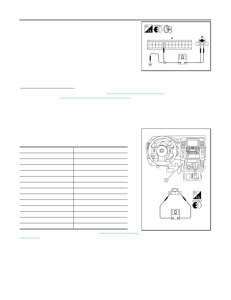
1. Turn ignition switch OFF.
2. Disconnect A/C auto amp. connector and in-vehicle sensor con-
nector.
3. Check continuity between in-vehicle sensor harness connector
M32 (B) terminal 3 and A/C auto amp. harness connector M50
(A) terminal 31.
4. Check continuity between in-vehicle sensor harness connector
M32 (B) terminal 3 and ground.
Is the inspection result normal?
YES
>> 1. Replace A/C auto amp. Refer to
VTL-7, "Removal and Installation"
.
2. Go to
HAC-24, "A/C Auto Amp. Self-Diagnosis"
and perform self-diagnosis.
NO
>> Repair harness or connector.
In-Vehicle Sensor Component Inspection
INFOID:0000000007356390
COMPONENT INSPECTION
In-vehicle Sensor
After disconnecting in-vehicle sensor connector M32, measure resis-
tance between terminals 1 and 4 at sensor component side, using
the table below.
If NG, replace in-vehicle sensor. Refer to
3 - 31
: Continuity should exist.
2 - Ground
: Continuity should exist.
3 - Ground
: Continuity should not exist.
AWIIA0168ZZ
Temperature
°
C (
°
F)
Resistance k
Ω
−
15 (5)
21.40
−
10 (14)
16.15
−
5 (23)
12.29
0 (32)
9.41
5 (41)
7.27
10 (50)
5.66
15 (59)
4.45
20 (68)
3.51
25 (77)
2.79
30 (86)
2.24
35 (95)
1.80
40 (104)
1.45
45 (113)
1.18
AWIIA0269ZZ
August 2012
2012 Pathfinder
OPTICAL SENSOR
HAC-85
< DTC/CIRCUIT DIAGNOSIS >
[AUTOMATIC AIR CONDITIONER]
C
D
E
F
G
H
J
K
L
M
A
B
HAC
N
O
P
OPTICAL SENSOR
Component Description
INFOID:0000000007356391
COMPONENT DESCRIPTION
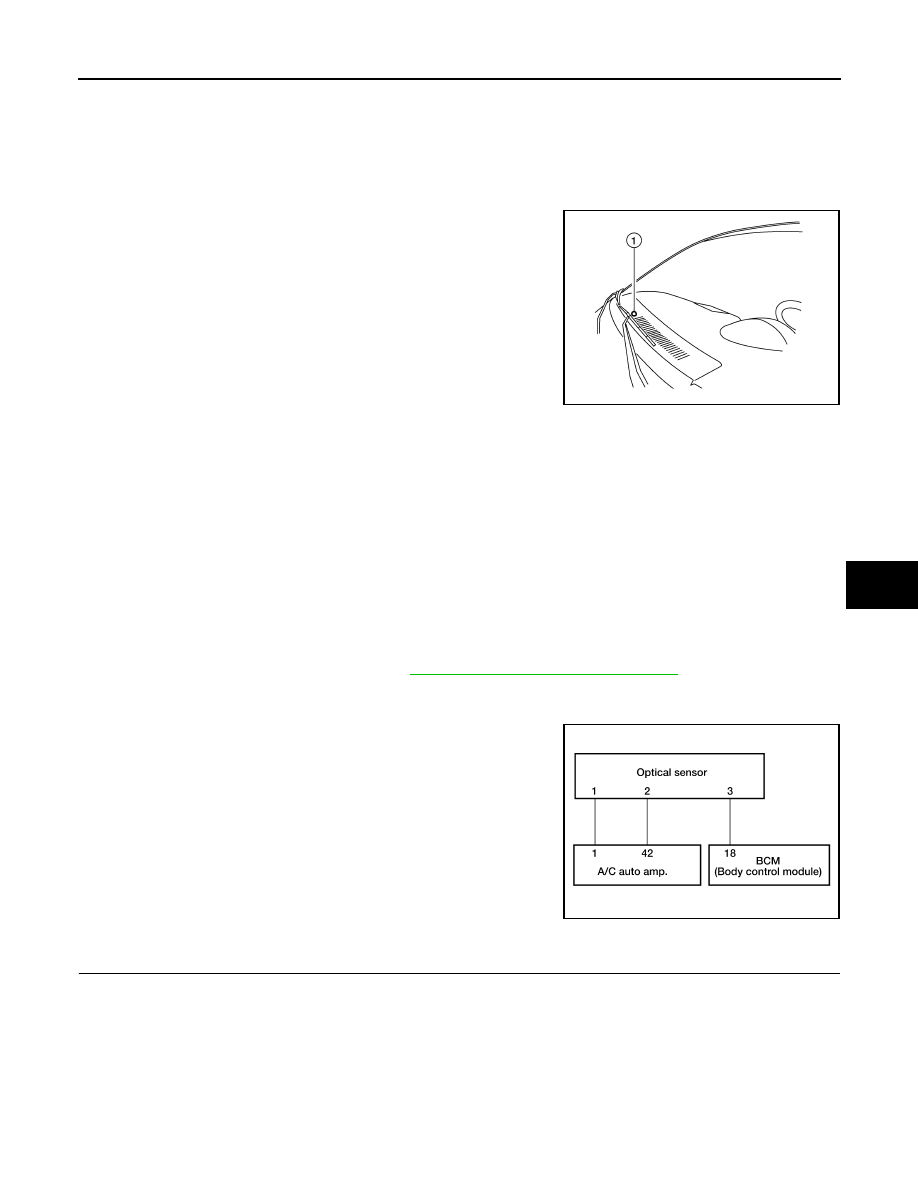
The optical sensor (1) is located in the center of the defroster grille. It
detects sunload entering through windshield by means of a photo
diode. The sensor converts the sunload into a current value which is
then input into the A/C auto amp.
OPTICAL INPUT PROCESS
The A/C auto amp. includes a processing circuit which averages the variations in detected sunload over a
period of time. This prevents adjustments in the ATC system operation due to small or quick variations in
detected sunload.
For example, consider driving along a road bordered by an occasional group of large trees. The sunload
detected by the optical sensor will vary whenever the trees obstruct the sunlight. The processing circuit aver-
ages the detected sunload over a period of time, so that the (insignificant) effect of the trees momentarily
obstructing the sunlight does not cause any change in the ATC system operation. On the other hand, shortly
after entering a long tunnel, the system will recognize the change in sunload, and the system will react accord-
ingly.
Optical Sensor Diagnosis Procedure
INFOID:0000000007356392
Regarding Wiring Diagram information, refer to
HAC-95, "Wiring Diagram - Automatic"
DIAGNOSTIC PROCEDURE FOR OPTICAL SENSOR
SYMPTOM: Optical sensor circuit is open or shorted. Using the
CONSULT, DTC B257F or B2580 is displayed. Without a CONSULT,
code 50 or 52 is indicated on A/C auto amp. as a result of conducting
self-diagnosis.
1.
CHECK CIRCUIT CONTINUITY BETWEEN OPTICAL SENSOR AND A/C AUTO AMP.
AWIIA0169ZZ
AWIIA1067GB
August 2012
2012 Pathfinder
HAC-86
< DTC/CIRCUIT DIAGNOSIS >
[AUTOMATIC AIR CONDITIONER]
OPTICAL SENSOR
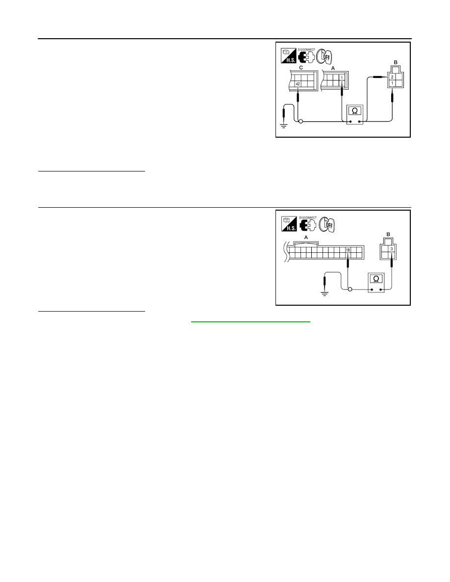
1. Turn ignition switch OFF.
2. Disconnect A/C auto amp. connector and optical sensor connec-
tor.
3. Check continuity between optical sensor harness connector
M145 (B) terminals 1 and 2 and A/C auto amp. harness connec-
tor M50 (C) terminal 42 and M49 (A) terminal 1.
4. Check continuity between optical sensor harness connector
M145 (B) terminal 1 and 2 and ground.
Is the inspection result normal?
YES
>> GO TO 2.
NO
>> Repair harness or connector.
2.
CHECK CIRCUIT CONTINUITY BETWEEN OPTICAL SENSOR AND BCM
1. Disconnect BCM connector.
2. Check continuity between optical sensor harness connector
M145 (B) terminal 3 and BCM harness connector M18 (A) termi-
nal 18.
3. Check continuity between optical sensor harness connector
M145 (B) terminal 3 and ground.
Is the inspection result normal?
YES
>> Replace optical sensor. Refer to
VTL-10, "Removal and Installation"
.
NO
>> Repair harness or connector.
1 - 1
: Continuity should exist.
2 - 42
: Continuity should exist.
1, 2 - Ground.
: Continuity should not exist.
AWIIA1072ZZ
3 - 18
: Continuity should exist.
3 - Ground
: Continuity should not exist.
AWIIA1068ZZ
August 2012
2012 Pathfinder
INTAKE SENSOR
HAC-87
< DTC/CIRCUIT DIAGNOSIS >
[AUTOMATIC AIR CONDITIONER]
C
D
E
F
G
H
J
K
L
M
A
B
HAC
N
O
P
INTAKE SENSOR
System Description
INFOID:0000000007356393
COMPONENT DESCRIPTION
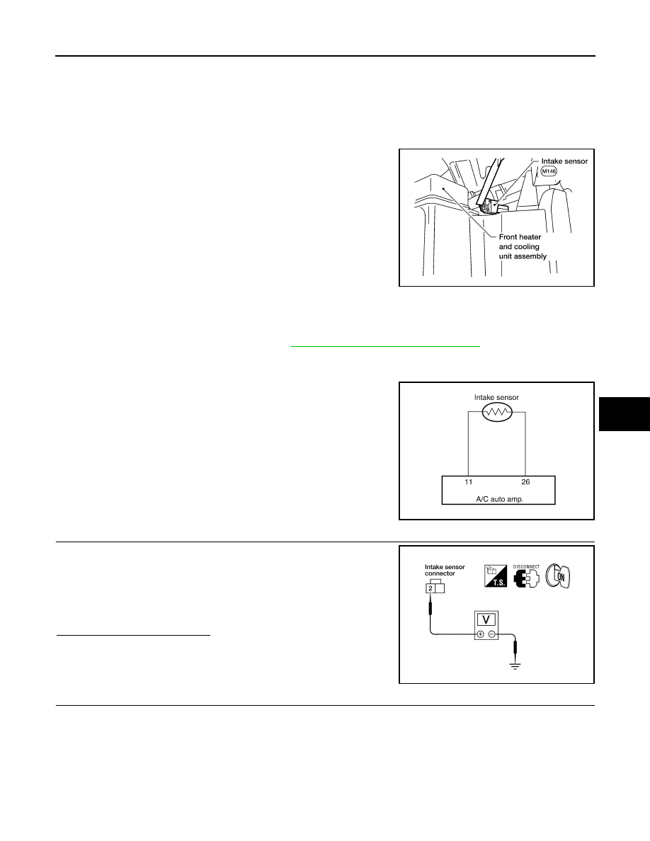
Intake Sensor
The intake sensor is located on the heater & cooling unit assembly. It
converts temperature of air after if passes through the evaporator
into a resistance value which is then input to the A/C auto amp.
Intake Sensor Diagnosis Procedure
INFOID:0000000007356394
Regarding Wiring Diagram information, refer to
HAC-95, "Wiring Diagram - Automatic"
DIAGNOSTIC PROCEDURE FOR INTAKE SENSOR
SYMPTOM: Intake sensor circuit is open or shorted. Using the CON-
SULT, DTC B2581 or B2582 is displayed. Without a CONSULT, code
56 or 57 is indicated on A/C auto amp. as a result of conducting self-
diagnosis.
1.
CHECK VOLTAGE BETWEEN INTAKE SENSOR AND GROUND
1. Disconnect intake sensor connector.
2. Turn ignition switch ON.
3. Check voltage between intake sensor harness connector M146
terminal 2 and ground.
Is the inspection result normal?
YES
>> GO TO 2.
NO
>> GO TO 4.
2.
CHECK CIRCUIT CONTINUITY BETWEEN INTAKE SENSOR AND A/C AUTO AMP.
WJIA1155E
AWIIA0208GB
2 - Ground
: Approx. 5V
WJIA1375E
August 2012
2012 Pathfinder
HAC-88
< DTC/CIRCUIT DIAGNOSIS >
[AUTOMATIC AIR CONDITIONER]
INTAKE SENSOR
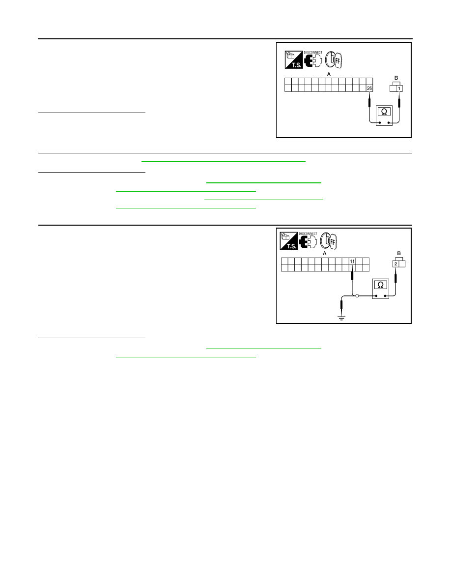
1. Turn ignition switch OFF.
2. Disconnect A/C auto amp. connector.
3. Check continuity between intake sensor harness connector
M146 (B) terminal 1 and A/C auto amp. harness connector M49
(A) terminal 26.
Is the inspection result normal?
YES
>> GO TO 3.
NO
>> Repair harness or connector.
3.
CHECK INTAKE SENSOR
Check intake sensor. Refer to
HAC-88, "Intake Sensor Component Inspection"
.
Is the inspection result normal?
YES
>> 1. Replace A/C auto amp. Refer to
VTL-7, "Removal and Installation"
.
2. Go to
HAC-24, "A/C Auto Amp. Self-Diagnosis"
and perform self-diagnosis.
NO
>> 1. Replace intake sensor. Refer to
VTL-11, "Removal and Installation"
.
2. Go to
HAC-24, "A/C Auto Amp. Self-Diagnosis"
and perform self-diagnosis.
4.
CHECK CIRCUIT CONTINUITY BETWEEN INTAKE SENSOR AND A/C AUTO AMP.
1. Turn ignition switch OFF.
2. Disconnect A/C auto amp. connector.
3. Check continuity between intake sensor harness connector
M146 (B) terminal 2 and A/C auto amp. harness connector M49
(A) terminal 11.
4. Check continuity between intake sensor harness connector
M146 (B) terminal 2 and ground.
Is the inspection result normal?
YES
>> 1. Replace A/C auto amp. Refer to
VTL-7, "Removal and Installation"
.
2. Go to
HAC-24, "A/C Auto Amp. Self-Diagnosis"
and perform self-diagnosis.
NO
>> Repair harness or connector.
Intake Sensor Component Inspection
INFOID:0000000007356395
COMPONENT INSPECTION
Intake Sensor
1 - 26
: Continuity should exist.
AWIIA0209ZZ
2 - 11
: Continuity should exist.
2 - Ground
: Continuity should not exist.
AWIIA0216ZZ
August 2012
2012 Pathfinder
INTAKE SENSOR
HAC-89
< DTC/CIRCUIT DIAGNOSIS >
[AUTOMATIC AIR CONDITIONER]
C
D
E
F
G
H
J
K
L
M
A
B
HAC
N
O
P
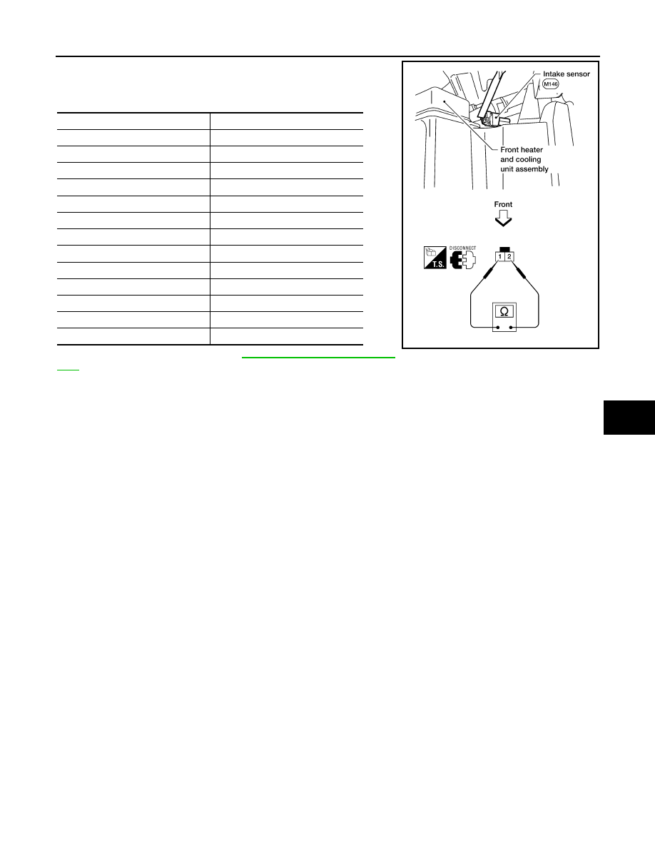
After disconnecting intake sensor connector, measure resistance
between terminals 1 and 2 at sensor harness side, using the table
below.
If NG, replace intake sensor. Refer to
VTL-11, "Removal and Installa-
.
Temperature
°
C (
°
F)
Resistance k
Ω
−
15 (5)
209.0
−
10 (14)
160.0
−
5 (23)
123.0
0 (32)
95.8
5 (41)
74.9
10 (50)
58.9
15 (59)
46.7
20 (68)
37.3
25 (77)
30.0
30 (86)
24.2
35 (95)
19.7
40 (104)
16.1
45 (113)
13.2
WJIA1159E
August 2012
2012 Pathfinder
Нет комментариевНе стесняйтесь поделиться с нами вашим ценным мнением.
Текст