Nissan Pathfinder (2012 year). Instruction — part 421
HAC-90
< DTC/CIRCUIT DIAGNOSIS >
[AUTOMATIC AIR CONDITIONER]
POWER SUPPLY AND GROUND CIRCUIT FOR CONTROLLER
POWER SUPPLY AND GROUND CIRCUIT FOR CONTROLLER
Component Description
INFOID:0000000007356396
COMPONENT DESCRIPTION
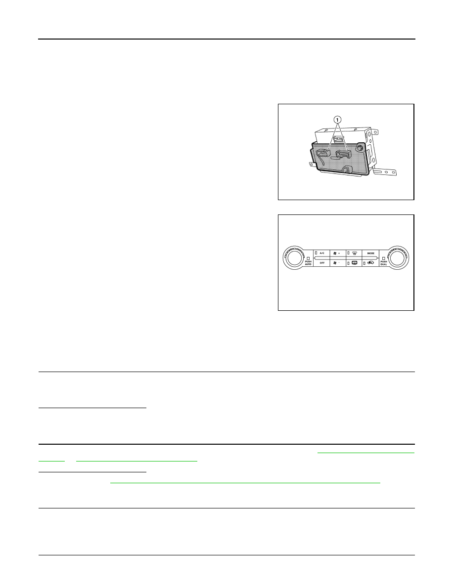
A/C auto amp.
The A/C auto amp. (1) has a built-in microcomputer which processes
information sent from various sensors needed for air conditioner
operation. The air mix door motors, mode door motor, intake door
motor, defroster door motor, blower motor and compressor are then
controlled.
The A/C auto amp. is unitized with control mechanisms. When the
various switches and temperature dials are operated, data is input to
the A/C auto amp.
Self-diagnostic functions are also built into the A/C auto amp. to pro-
vide quick check of malfunctions in the auto air conditioner system.
Potentio Temperature Control (PTC)
There are two PTCs (driver and passenger) built into the A/C auto
amp. They can be set at an interval of 0.5
°
C (1.0
°
F) in the 18
°
C
(60
°
F) to 32
°
C (90
°
F) temperature range by rotating the temperature
dial. The set temperature is displayed.
A/C Auto Amp. Component Function Check
INFOID:0000000007356397
SYMPTOM: A/C system does not come on.
INSPECTION FLOW
1.
CONFIRM SYMPTOM BY PERFORMING OPERATIONAL CHECK - AUTO MODE
1. Press AUTO switch.
2. Display should indicate AUTO. Confirm that the compressor clutch engages (sound or visual inspection).
(Discharge air and blower speed will depend on ambient, in-vehicle and set temperatures.)
Is the inspection result normal?
YES
>> GO TO 3.
NO
>> GO TO 2.
2.
PERFORM COMPLETE OPERATIONAL CHECK
Perform a complete operational check and check for any symptoms. Refer to
HAC-6, "Operational Check (Rear)"
.
Is the inspection result normal?
YES
>> Refer to
HAC-128, "How to Perform Trouble Diagnosis For Quick And Accurate Repair"
NO
>> System OK.
3.
CHECK FOR SERVICE BULLETINS
Check for any service bulletins.
>> GO TO 4.
4.
CHECK POWER AND GROUND CIRCUIT
AWIIA0170ZZ
AWIIA0211GB
August 2012
2012 Pathfinder
POWER SUPPLY AND GROUND CIRCUIT FOR CONTROLLER
HAC-91
< DTC/CIRCUIT DIAGNOSIS >
[AUTOMATIC AIR CONDITIONER]
C
D
E
F
G
H
J
K
L
M
A
B
HAC
N
O
P
Check main power supply and ground circuit. Refer to
HAC-91, "A/C Auto Amp Power and Ground Diagnosis
.
Is the inspection result normal?
YES
>> System OK.
NO
>> Replace A/C auto amp. Refer to
VTL-7, "Removal and Installation"
.
A/C Auto Amp Power and Ground Diagnosis Procedure
INFOID:0000000007356398
Regarding Wiring Diagram information, refer to
HAC-95, "Wiring Diagram - Automatic"
DIAGNOSTIC PROCEDURE FOR A/C SYSTEM
SYMPTOM: A/C system does not come on.
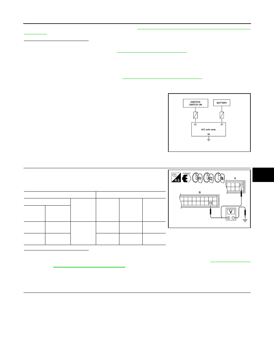
1.
CHECK POWER SUPPLY CIRCUITS FOR A/C AUTO AMP.
1. Disconnect A/C auto amp. connectors.
2. Check voltage between A/C auto amp. harness connector M49
(B) terminal 15 and M50 (A) terminal 27, and ground.
Is the inspection result normal?
YES
>> GO TO 2.
NO
>> Check 10A fuses [Nos. 8 and 19, located in the fuse block (J/B)]. Refer to
Amp. Terminals Reference Values"
• If fuses are OK, check harness for open circuit. Repair or replace as necessary.
• If fuses are NG, replace fuse and check harness for short circuit. Repair or replace as neces-
sary.
2.
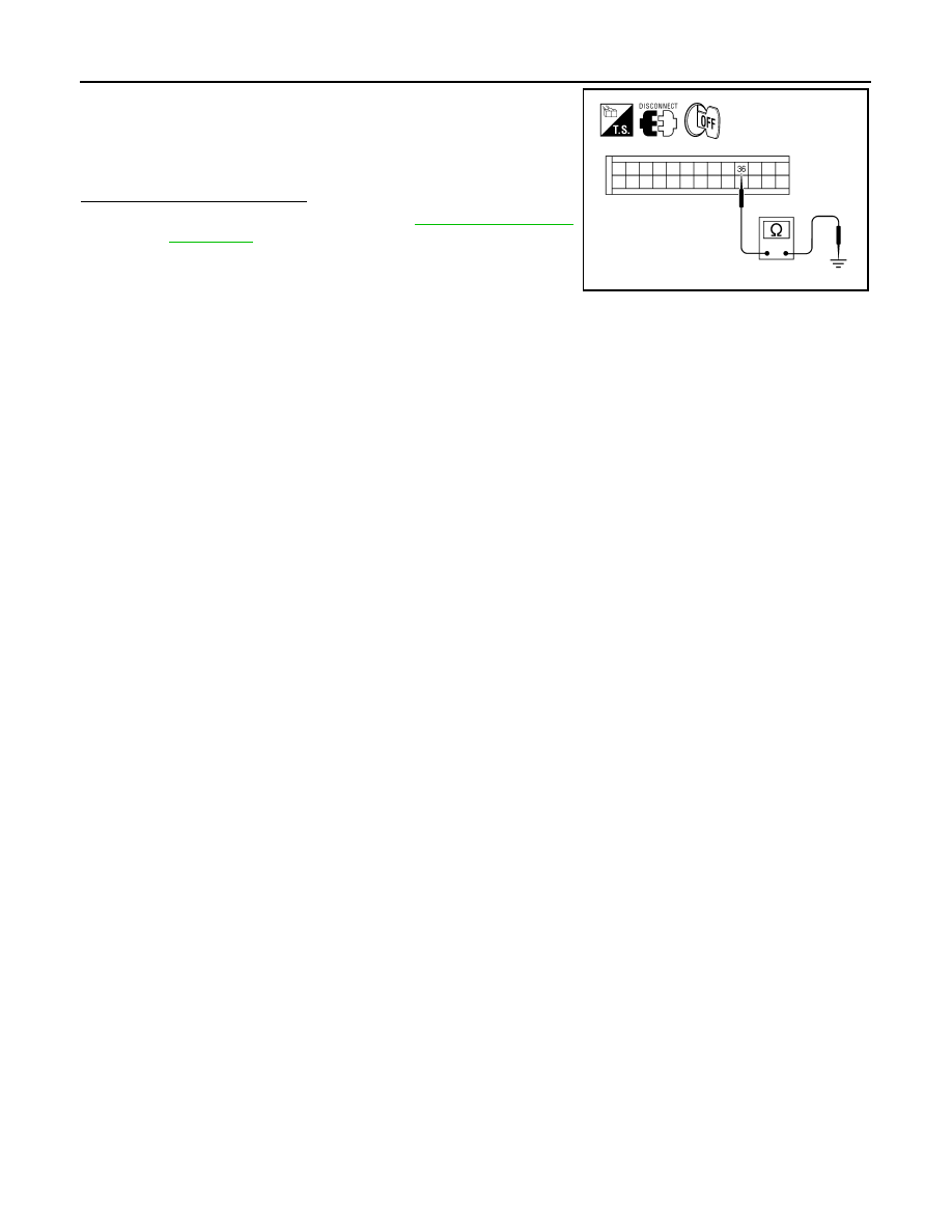
CHECK GROUND CIRCUIT FOR A/C AUTO AMP.
AWIIA0212GB
Terminals
Ignition switch position
(+)
(-)
OFF
ACC
ON
A/C auto
amp. con-
nector
Terminal No.
M49
15
Ground
Approx. 0V
Approx. 0V
Battery
voltage
M50
27
Battery
voltage
Battery
voltage
Battery
voltage
AWIIA1047ZZ
August 2012
2012 Pathfinder
HAC-92
< DTC/CIRCUIT DIAGNOSIS >
[AUTOMATIC AIR CONDITIONER]
POWER SUPPLY AND GROUND CIRCUIT FOR CONTROLLER
1. Turn ignition switch OFF.
2. Check continuity between A/C auto amp. harness connector
M50 terminal 36 and ground.
Is the inspection result normal?
OK
>> Replace A/C auto amp. Refer to
NG
>> Repair harness or connector.
36 - Ground
: Continuity should exist.
AWIIA0214ZZ
August 2012
2012 Pathfinder
AIR CONDITIONER CONTROL
HAC-93
< ECU DIAGNOSIS INFORMATION >
[AUTOMATIC AIR CONDITIONER]
C
D
E
F
G
H
J
K
L
M
A
B
HAC
N
O
P
ECU DIAGNOSIS INFORMATION
AIR CONDITIONER CONTROL
A/C Auto Amp. Terminals Reference Values
INFOID:0000000007356399
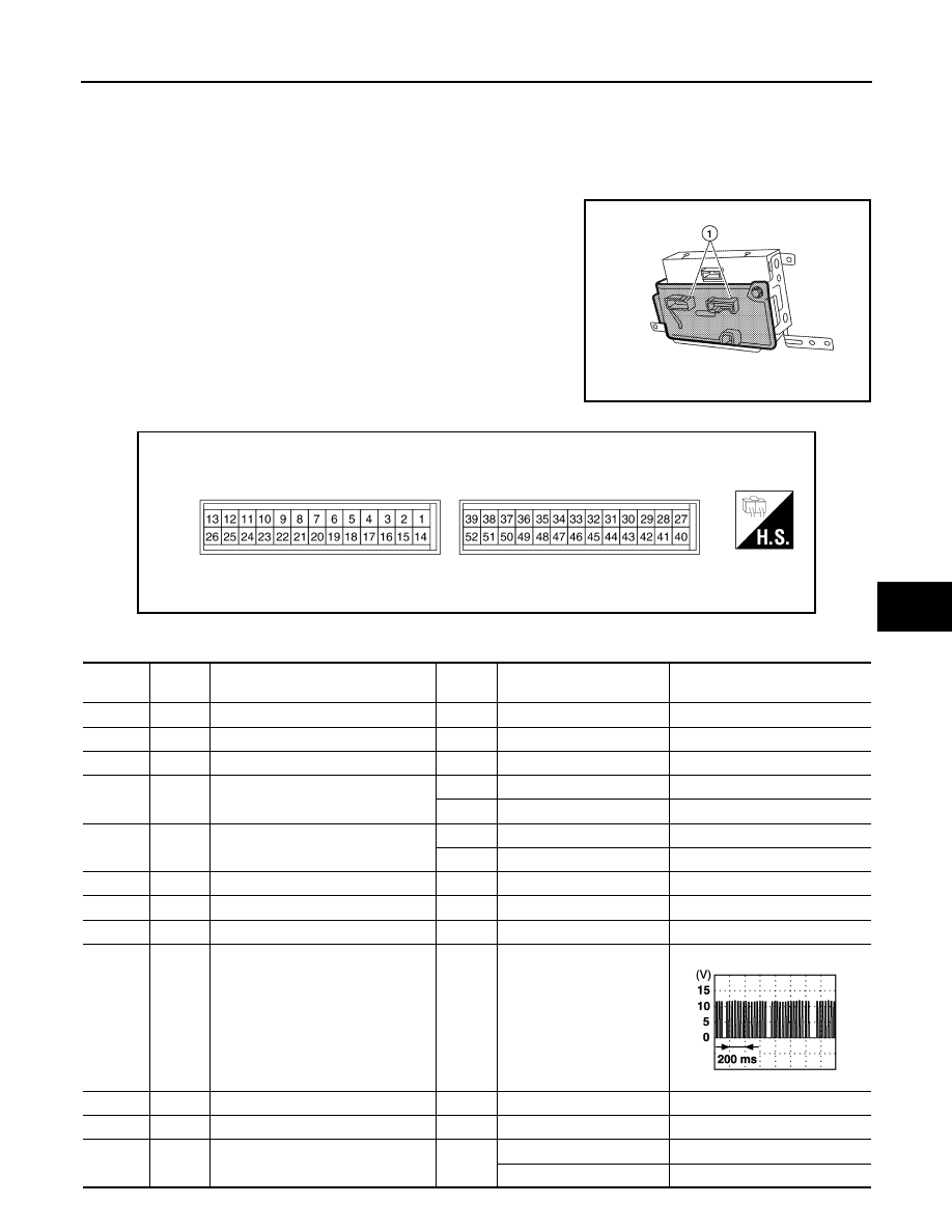
Measure voltage between each terminal and ground by following
Terminals and Reference Value for A/C auto amp. (1).
A/C AUTO AMP. HARNESS CONNECTOR TERMINAL LAYOUT
TERMINALS AND REFERENCE VALUES FOR A/C AUTO AMP.
AWIIA0170ZZ
AWIIA0840ZZ
Terminal
No.
Wire
color
Item
Ignition
switch
Condition
Voltage (V)
(Approx.)
1
G
Optical sensor (driver)
ON
-
0 - 5V
2
L
Air mix door motor (passenger) CCW
ON
-
0 - 5V
3
G
V ref ACTR (ground)
ON
-
5V
4
W
Compressor ON signal
ON
A/C switch OFF
5V
ON
A/C switch ON
0V
5
R
Fan ON signal
ON
Blower switch OFF
5V
ON
Blower switch ON
0V
6
SB
Air mix door motor (driver) feedback
ON
-
0 - 5V
7
V
Mode door motor (front) feedback
ON
-
0 - 5V
8
G
Illumination +
ON
Park lamps ON
Battery voltage
9
BR
Illumination -
-
Park lamps ON
11
L
Intake sensor
ON
-
0 - 5V
12
P
Variable blower control (rear)
ON
-
0 - 5V
13
R
Variable blower control (front)
ON
Blower speed (low)
1.7V
Blower speed (high)
4.5V
PIIA2344E
August 2012
2012 Pathfinder

HAC-94
< ECU DIAGNOSIS INFORMATION >
[AUTOMATIC AIR CONDITIONER]
AIR CONDITIONER CONTROL
14
LG
Air mix door motor (passenger) CW
ON
Clockwise rotation
Battery voltage
15
W/G
Power supply for IGN
ON
-
Battery voltage
17
GR
Air mix door motor (driver) CW
ON
Clockwise rotation
Battery voltage
18
BR
Air mix door motor (driver) CCW
ON
Counterclockwise rotation
Battery voltage
19
L
Mode door motor CW (front)
ON
Clockwise rotation
Battery voltage
20
B/R
Mode door motor CCW
ON
Counterclockwise rotation
Battery voltage
21
O
Intake door motor CCW
ON
Counterclockwise rotation
Battery voltage
22
O
Intake door motor CW
ON
Clockwise rotation
Battery voltage
25
W
Ambient sensor
ON
-
0 - 5V
26
V
Sensor ground
ON
-
0V
27
R/Y
Power supply for BAT
-
-
Battery voltage
28
P
V ref ACTR (5V)
ON
-
0 - 5V
29
SB
Air mix door motor (passenger) feed-
back
ON
-
0 - 5V
30
R
Air mix door motor (Rear) feedback
ON
-
0 - 5V
31
BR
In-vehicle sensor motor (+)
ON
-
Battery voltage
32
LG
In-vehicle sensor signal
ON
-
0 - 5V
34
GY
Front aux backlight dim
ON
Headlamps OFF
Battery voltage
35
W/G
Front aux tell tale LED
ON
Tell tale OFF
Battery voltage
36
B
Ground
-
-
0V
37
GR
Front aux temp pot
ON
Rear air control (front) tem-
perature control dial
0 - 5V
38
P
Front aux blower pot
ON
Rear air control (front)
blower motor
0 - 5V
39
SB
Front AUX (rear)
ON
-
0 - 5V
40
P
CAN-L
ON
-
0 - 5V
41
L
CAN-H
ON
-
0 - 5V
42
GR
Optical sensor (passenger)
ON
-
0 - 5V
43
V
Air mix door motor (Rear) CW
ON
Clockwise rotation
Battery voltage
44
O
Air mix door motor (Rear) CCW
ON
Counterclockwise rotation
Battery voltage
45
P
Water valve (VK56DE)
ON
Water valve open
Battery voltage
Water valve closed
0V
46
R
Water valve (VK56DE)
ON
Water valve open
0V
Water valve closed
Battery voltage
50
GR
Heater pump request (VQ40DE)
ON
Heater pump on
0V
Heater pump off
Battery voltage
51
L
Rear aux temp pot
ON
Rear air control (rear) tem-
perature control dial
0 - 5V
52
W
Rear aux blower pot
ON
Rear blower motor
0 - 5V
Terminal
No.
Wire
color
Item
Ignition
switch
Condition
Voltage (V)
(Approx.)
August 2012
2012 Pathfinder
AIR CONDITIONER CONTROL
HAC-95
< WIRING DIAGRAM >
[AUTOMATIC AIR CONDITIONER]
C
D
E
F
G
H
J
K
L
M
A
B
HAC
N
O
P
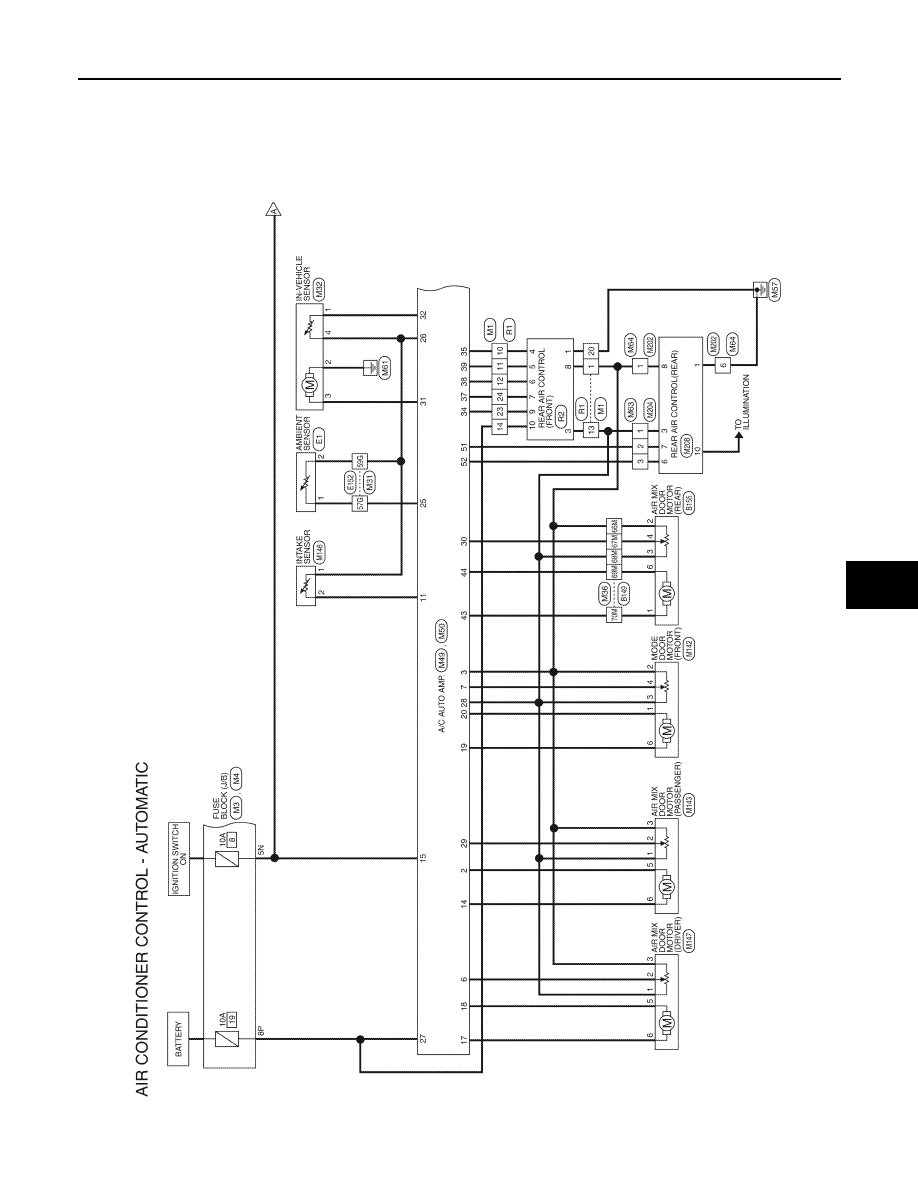
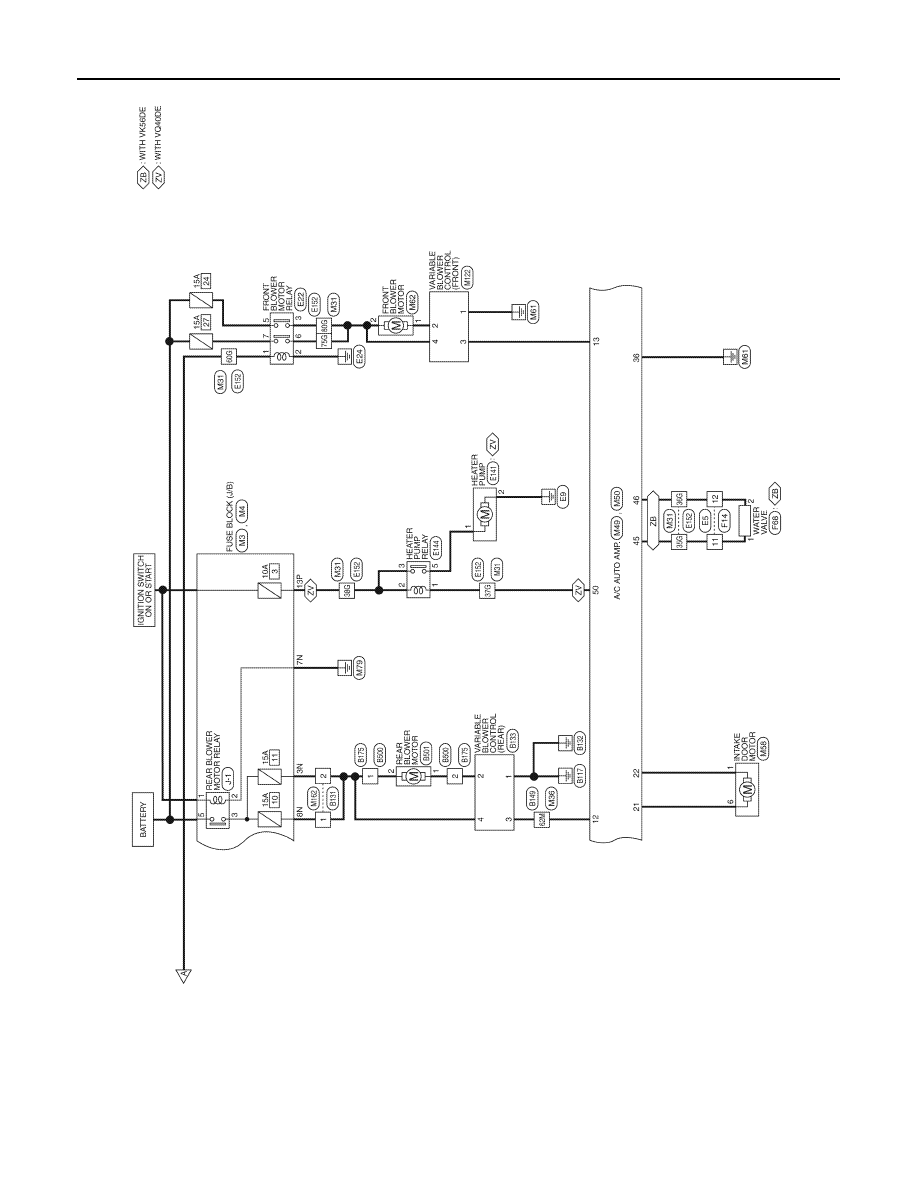
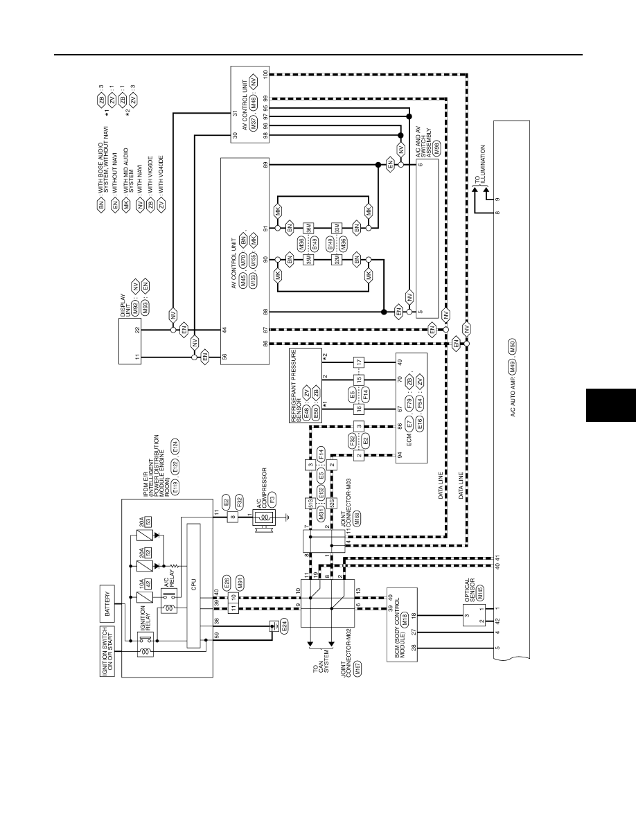
WIRING DIAGRAM
AIR CONDITIONER CONTROL
Wiring Diagram - Automatic
INFOID:0000000007356400
ABIWA0083GB
August 2012
2012 Pathfinder
HAC-96
< WIRING DIAGRAM >
[AUTOMATIC AIR CONDITIONER]
AIR CONDITIONER CONTROL
ABIWA0080GB
August 2012
2012 Pathfinder
AIR CONDITIONER CONTROL
HAC-97
< WIRING DIAGRAM >
[AUTOMATIC AIR CONDITIONER]
C
D
E
F
G
H
J
K
L
M
A
B
HAC
N
O
P
ABIWA0224GB
August 2012
2012 Pathfinder
Нет комментариевНе стесняйтесь поделиться с нами вашим ценным мнением.
Текст