Nissan Pathfinder (2012 year). Instruction — part 185

P1816 PNP SWITCH
DLN-45
< DTC/CIRCUIT DIAGNOSIS >
[TRANSFER: ATX14B]
C
E
F
G
H
I
J
K
L
M
A
B
DLN
N
O
P
P1816 PNP SWITCH
Description
INFOID:0000000007357381
The transmission range switch transmits the A/T position indicator signal (transmission range switch signal)
via CAN communication to the transfer control unit. DTC P1816 will set when the transmission range switch
signal is malfunctioning or there is a communication error.
DTC Logic
INFOID:0000000007357382
DTC DETECTION LOGIC
DTC CONFIRMATION PROCEDURE
1.
DTC CONFIRMATION PROCEDURE
1. Turn ignition switch ON.
2. Perform self-diagnosis.
Is DTC P1816 displayed?
YES
>> Perform diagnosis procedure. Refer to
.
NO
>> Inspection End.
Diagnosis Procedure
INFOID:0000000007357383
1.
CHECK DTC WITH TCM
Perform self-diagnosis with TCM. Refer to
TM-37, "CONSULT Function (TRANSMISSION)"
Is any malfunction detected by self-diagnosis?
YES
>> Check the malfunctioning system.
NO
>> GO TO 2.
2.
CHECK TRANSFER CONTROL UNIT
Check transfer control unit input/output signal. Refer to
Are inspection results normal?
YES
>> GO TO 3.
NO
>> Check transfer control unit pin terminals for damage or loose connection with harness connector.
If any items are damaged, repair or replace damaged parts.
3.
CHECK DTC
Drive the vehicle and then perform self-diagnosis.
Are inspection results normal?
YES
>> Inspection End.
NO
>> Perform self-diagnosis with TCM again.
DTC
CONSULT
Diagnostic item is detected when...
Reference
[P1816]
PNP SW/CIRC
When transmission range switch signal
is malfunction or communication error
between the control units.
August 2012
2012 Pathfinder

DLN-46
< DTC/CIRCUIT DIAGNOSIS >
[TRANSFER: ATX14B]
P1817 ACTUATOR MOTOR
P1817 ACTUATOR MOTOR
Description
INFOID:0000000007357384
The actuator motor receives signals from the transfer control unit and controls shift rods which shift the trans-
fer case. DTC P1817 will set when any of the following occur:
• Motor does not operate properly due to open or short circuit in actuator motor.
• Malfunction is detected in the actuator motor. (When 4WD shift switch is operated and actuator motor does
not operate)
• Malfunction is detected in transfer shift high relay or transfer shift low relay.
DTC Logic
INFOID:0000000007357385
DTC DETECTION LOGIC
DTC CONFIRMATION PROCEDURE
1.
DTC CONFIRMATION PROCEDURE
1. Turn ignition switch ON.
2. Perform self-diagnosis.
Is DTC P1817 detected?
YES
>> Perform diagnosis procedure. Refer to
.
NO
>> Inspection End.
Diagnosis Procedure
INFOID:0000000007357386
Regarding Wiring Diagram information, refer to
1.
CHECK ACTUATOR MOTOR SIGNAL
With CONSULT
1. Start engine.
2. Select “DATA MONITOR” mode for “ALL MODE AWD/4WD” with CONSULT.
3. Read out the value of “SHIFT ACT1”, “SHIFT AC MON1”, “SHIFT ACT2” and “SHIFT AC MON2”.
DTC
CONSULT
Diagnostic item is detected when...
Reference
[P1817]
SHIFT ACTUATOR
• Motor does not operate properly due
to open or short circuit in actuator mo-
tor.
• Malfunction is detected in the actuator
motor. (When 4WD shift switch is op-
erated and actuator motor is not oper-
ated)
• Malfunction is detected in transfer shift
high relay and transfer shift low relay.
Refer to
.
Monitored
item
Condition
Display
value
SHIFT ACT1
• Vehicle stopped
• Engine running
• A/T selector lever “N” posi-
tion
• Brake pedal depressed
4WD shift switch: 4H
to 4LO (“Wait” func-
tion is operating.)
ON
Except the above
OFF
August 2012
2012 Pathfinder
P1817 ACTUATOR MOTOR
DLN-47
< DTC/CIRCUIT DIAGNOSIS >
[TRANSFER: ATX14B]
C
E
F
G
H
I
J
K
L
M
A
B
DLN
N
O
P
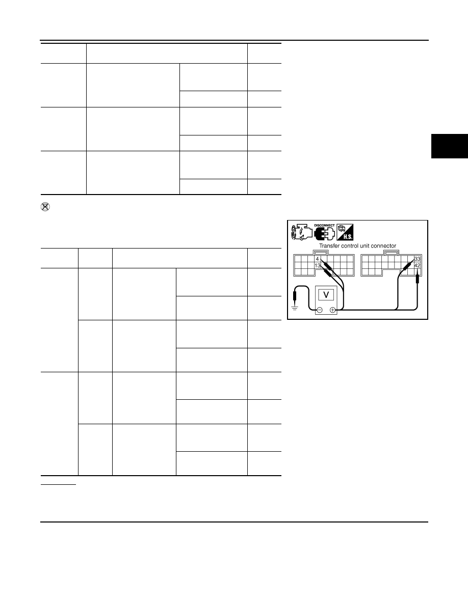
Without CONSULT
1. Start engine.
2. Check voltage between transfer control unit harness connector
terminal and ground.
OK or NG
OK
>> GO TO 7.
NG
>> GO TO 2.
2.
CHECK ACTUATOR MOTOR POWER SUPPLY CIRCUIT
1. Turn ignition switch “OFF”. (Stay for at least 5 seconds.)
2. Remove transfer shift high relay and transfer shift low relay.
SHIFT AC
MON1
• Vehicle stopped
• Engine running
• A/T selector lever “N” posi-
tion
• Brake pedal depressed
4WD shift switch: 4H
to 4LO (“Wait” func-
tion is operating.)
ON
Except the above
OFF
SHIFT ACT2
• Vehicle stopped
• Engine running
• A/T selector lever “N” posi-
tion
• Brake pedal depressed
4WD shift switch:
4LO to 4H (“Wait”
function is operating.)
ON
Except the above
OFF
SHIFT AC
MON2
• Vehicle stopped
• Engine running
• A/T selector lever “N” posi-
tion
• Brake pedal depressed
4WD shift switch:
4LO to 4H (“Wait”
function is operating.)
ON
Except the above
OFF
Connector
Terminal
Condition
Voltage
(Approx.)
M152
4 -
Ground
• Vehicle stopped
• Engine running
• A/T selector lever
“N” position
• Brake pedal de-
pressed
4WD shift switch: 4H to
4LO (“Wait” function is
operating.)
Battery
voltage
Except the above
0V
13 -
Ground
• Vehicle stopped
• Engine running
• A/T selector lever
“N” position
• Brake pedal de-
pressed
4WD shift switch: 4LO
to 4H (“Wait” function
is operating.)
Battery
voltage
Except the above
0V
M153
33 -
Ground
• Vehicle stopped
• Engine running
• A/T selector lever
“N” position
• Brake pedal de-
pressed
4WD shift switch: 4H to
4LO (“Wait” function is
operating.)
Battery
voltage
Except the above
0V
42 -
Ground
• Vehicle stopped
• Engine running
• A/T selector lever
“N” position
• Brake pedal de-
pressed
4WD shift switch: 4LO
to 4H (“Wait” function
is operating.)
Battery
voltage
Except the above
0V
Monitored
item
Condition
Display
value
SDIA2705E
August 2012
2012 Pathfinder
DLN-48
< DTC/CIRCUIT DIAGNOSIS >
[TRANSFER: ATX14B]
P1817 ACTUATOR MOTOR
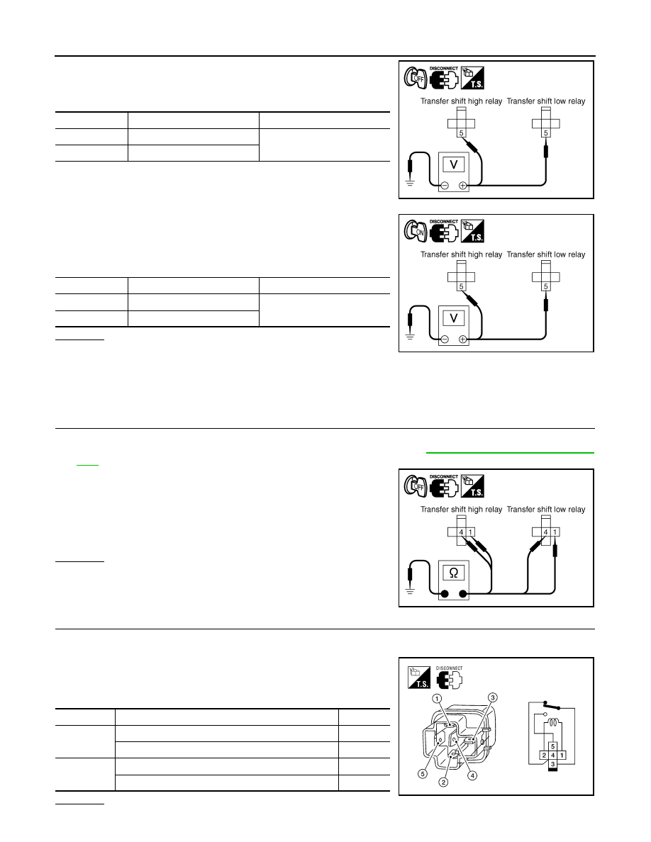
3. Check voltage between transfer shift high relay harness connec-
tor E46 terminal 5, transfer shift low relay harness connector
E47 terminal 5 and ground.
4. Turn ignition switch “ON”. (Do not start engine.)
5. Check voltage between transfer shift high relay harness connec-
tor E46 terminal 5, transfer shift low relay harness connector
E47 terminal 5 and ground.
OK or NG
OK
>> GO TO 3.
NG
>> Check the following. If any items are damaged, repair or replace damaged parts.
• 20A fuse (No. 58, located in the fuse and relay box).
• Harness for short or open between battery, transfer shift high harness connector terminal 5 and
transfer shift low harness connector terminal 5.
3.
CHECK ACTUATOR MOTOR GROUND CIRCUIT
1. Turn ignition switch “OFF”. (Stay for at least 5 seconds.)
2. Remove transfer shift high relay and transfer shift low relay. Refer to
DLN-19, "Component Parts Loca-
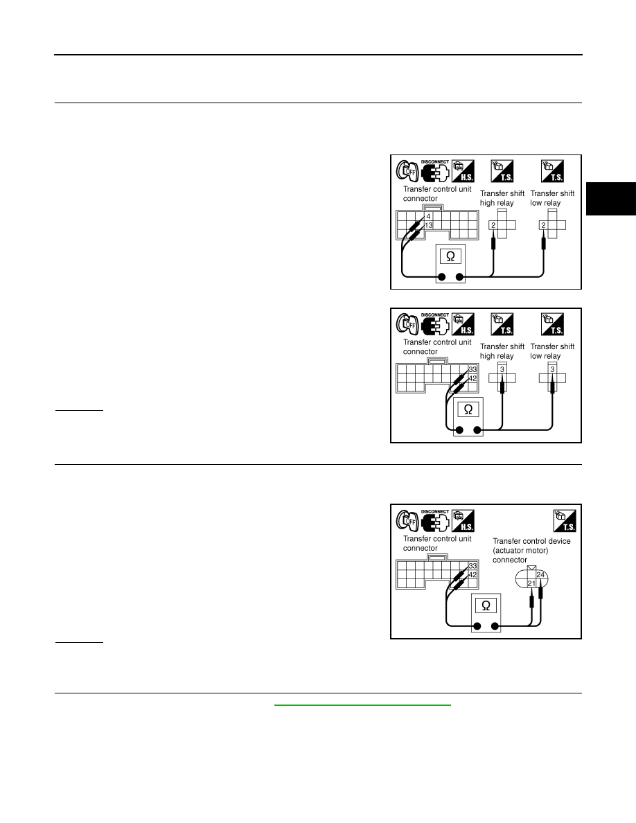
3. Check continuity between transfer shift high relay harness con-
nector E46 terminals 1 and 4, and transfer shift low relay har-
ness connector E47 terminals 1 and 4 and ground.
Also check harness for short to power.
OK or NG
OK
>> GO TO 4.
NG
>> Repair open circuit or short to power in harness or con-
nectors.
4.
CHECK TRANSFER SHIFT RELAYS
1. Turn ignition switch “OFF”.
2. Remove transfer shift high relay and transfer shift low relay.
3. Apply 12V direct current between transfer shift relay terminals 1
and 2.
4. Check continuity between relay terminals 3 and 4, 3 and 5.
OK or NG
Connector
Terminal
Voltage (Approx.)
E46
5 - Ground
Battery voltage
E47
5 - Ground
SDIA2707E
Connector
Terminal
Voltage (Approx.)
E46
5 - Ground
Battery voltage
E47
5 - Ground
SDIA2706E
Continuity should exist.
SDIA2708E
Terminal
Condition
Continuity
3 - 4
12V direct current supply between terminals 1 and 2
No
OFF
Yes
3 - 5
12V direct current supply between terminals 1 and 2
Yes
OFF
No
LDIA0099E
August 2012
2012 Pathfinder
P1817 ACTUATOR MOTOR
DLN-49
< DTC/CIRCUIT DIAGNOSIS >
[TRANSFER: ATX14B]
C
E
F
G
H
I
J
K
L
M
A
B
DLN
N
O
P
OK
>> GO TO 5.
NG
>> Replace the transfer shift relay.
5.
CHECK HARNESS BETWEEN TRANSFER CONTROL UNIT AND TRANSFER SHIFT RELAY
1. Turn ignition switch “OFF”. (Stay for at least 5 seconds.)
2. Disconnect transfer control unit harness connector and the transfer control device (actuator motor) har-
ness connector.
3. Remove transfer shift high relay and transfer shift low relay.
4. Check continuity between the following terminals.
-
Transfer control unit harness connector M152 terminal 4 and
transfer shift high relay harness connector E46 terminal 2.
-
Transfer control unit harness connector M152 terminal 13 and
transfer shift low relay harness connector E47 terminal 2.
-
Transfer control unit harness connector M153 terminal 33 and
transfer shift high relay harness connector E46 terminal 3.
-
Transfer control unit harness connector M153 terminal 42 and
transfer shift low relay harness connector E47 terminal 3.
Also check harness for short to ground and short to power.
OK or NG
OK
>> GO TO 6.
NG
>> Repair or replace damaged parts.
6.
CHECK HARNESS BETWEEN TRANSFER CONTROL UNIT AND ACTUATOR MOTOR
1. Turn ignition switch “OFF”. (Stay for at least 5 seconds.)
2. Disconnect transfer control unit harness connector and the transfer control device (actuator motor) har-
ness connector.
3. Check continuity between the following terminals.
-
Transfer control unit harness connector M153 terminal 33 and
transfer control device (actuator motor) harness connector F58
terminal 21.
-
Transfer control unit harness connector M153 terminal 42 and
transfer control device (actuator motor) harness connector F58
terminal 24.
Also check harness for short to ground and short to power.
OK or NG
OK
>> GO TO 7.
NG
>> Repair or replace damaged parts.
7.
CHECK ACTUATOR MOTOR
1. Remove transfer control device. Refer to
DLN-146, "Removal and Installation"
SDIA2711E
Continuity should exist.
SDIA2712E
Continuity should exist.
SDIA2710E
August 2012
2012 Pathfinder
DLN-50
< DTC/CIRCUIT DIAGNOSIS >
[TRANSFER: ATX14B]
P1817 ACTUATOR MOTOR
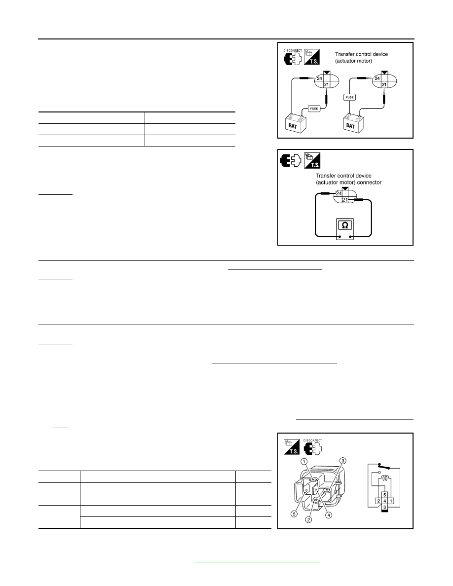
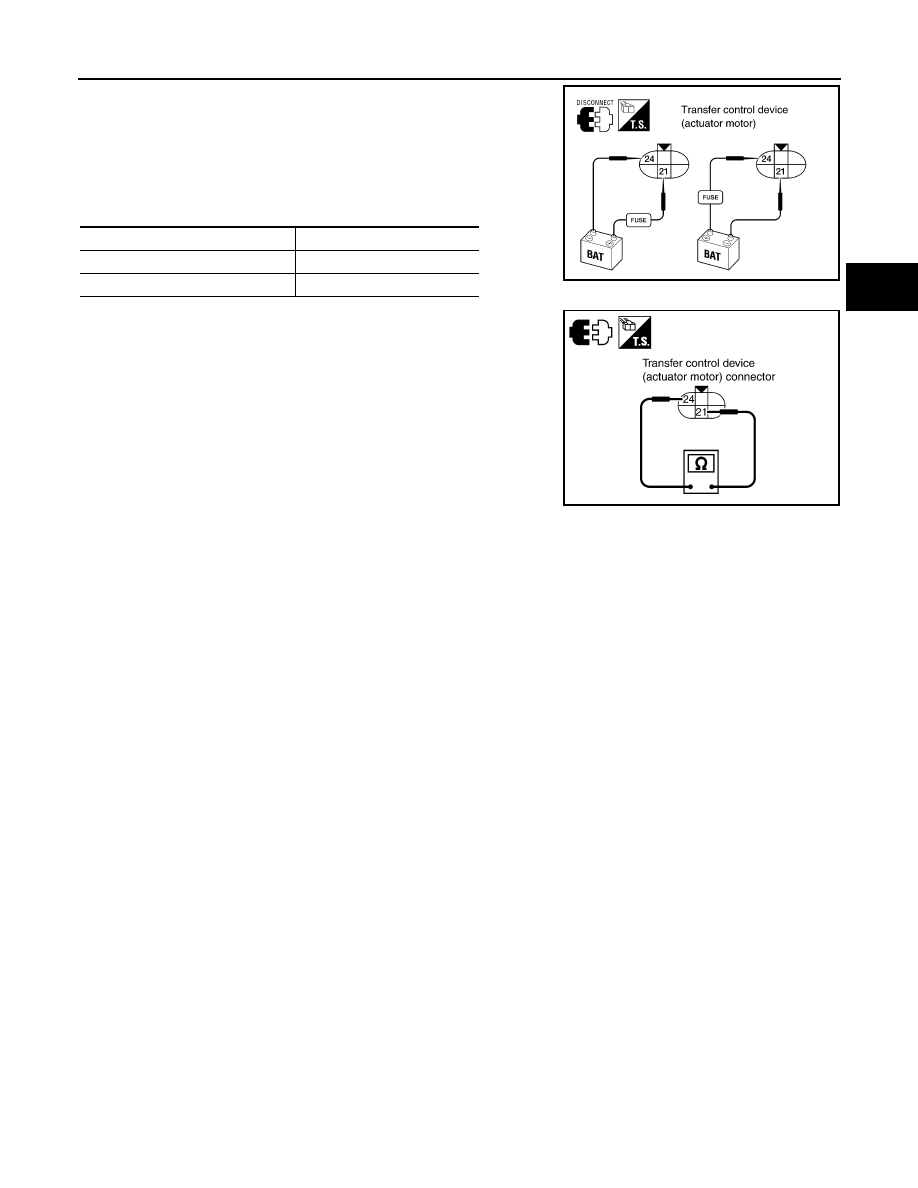
2. Check operation by applying battery voltage to transfer control
device (actuator motor) terminals 21 and 24.
CAUTION:
• Do not operate actuator motor for more than 1 second.
• Change the actuator motor position to “HIGH” when
installing.
• Be careful not to overheat the harness.
3. Check resistance between transfer control device (actuator
motor) terminals 21 and 24.
OK or NG
OK
>> GO TO 8.
NG
>> Replace transfer control device (actuator motor).
8.
CHECK TRANSFER CONTROL UNIT
Check transfer control unit input/output signal. Refer to
OK or NG
OK
>> GO TO 9.
NG
>> Check transfer control unit pin terminals for damage or loose connection with harness connector.
If any items are damaged, repair or replace damaged parts.
9.
CHECK DTC
Perform the self-diagnosis, after driving a vehicle for a while.
OK or NG
OK
>> Inspection End.
NG
>> Replace transfer control unit. Refer to
DLN-140, "Removal and Installation"
.
Component Inspection
INFOID:0000000007357387
TRANSFER SHIFT RELAY
1. Turn ignition switch “OFF”. (Stay for at least 5 seconds.)
2. Remove transfer shift high relay and transfer shift low relay. Refer to
DLN-19, "Component Parts Loca-
3. Apply 12V direct current between transfer shift relay terminals 1
and 2.
4. Check continuity between relay terminals 3 and 4, 3 and 5.
5. If NG, replace transfer shift relay.
TRANSFER CONTROL DEVICE
1. Remove transfer control device. Refer to
DLN-146, "Removal and Installation"
Terminal
Actuator motor
21 (Battery voltage) - 24 (Ground)
Clockwise rotate
24 (Battery voltage) - 21 (Ground)
Counterclockwise rotate
21 - 24 : Approx. 0.2
Ω
WDIA0224E
SDIA3252E
Terminal
Condition
Continuity
3 - 4
12V direct current supply between terminals 1 and 2
Yes
OFF
No
3 - 5
12V direct current supply between terminals 1 and 2
Yes
OFF
No
LDIA0099E
August 2012
2012 Pathfinder
P1817 ACTUATOR MOTOR
DLN-51
< DTC/CIRCUIT DIAGNOSIS >
[TRANSFER: ATX14B]
C
E
F
G
H
I
J
K
L
M
A
B
DLN
N
O
P
2. Check operation by applying battery voltage to transfer control
device (actuator motor) terminals 21 and 24.
CAUTION:
• Do not operate actuator motor for more than 1 second.
• Change the actuator motor position to “HIGH” when
installing.
• Be careful not to overheat the harness.
3. Check resistance between transfer control device (actuator
motor) terminals 21 and 24.
4. If NG, replace transfer control device (actuator motor).
Terminal
Actuator motor
21 (Battery voltage) - 24 (Ground)
Clockwise rotate
24 (Battery voltage) - 21 (Ground)
Counterclockwise rotate
WDIA0224E
21 - 24 : Approx. 0.2
Ω
SDIA3252E
August 2012
2012 Pathfinder

DLN-52
< DTC/CIRCUIT DIAGNOSIS >
[TRANSFER: ATX14B]
P1818 ACTUATOR POSITION SWITCH
P1818 ACTUATOR POSITION SWITCH
Description
INFOID:0000000007357388
The actuator position switch detects the current actuator motor range. DTC P1818 will set if either of the fol-
lowing occur:
• Improper signal from actuator position switch is input due to open or short circuit.
• Malfunction is detected in actuator position switch.
DTC Logic
INFOID:0000000007357389
DTC DETECTION LOGIC
DTC CONFIRMATION PROCEDURE
1.
DTC CONFIRMATION PROCEDURE
1. Turn ignition switch ON.
2. Perform self-diagnosis.
Is DTC P1818 detected?
YES
>> Perform diagnosis procedure. Refer to
.
NO
>> Inspection End.
Diagnosis Procedure
INFOID:0000000007357390
Regarding Wiring Diagram information, refer to
1.
CHECK ACTUATOR POSITION SWITCH SIGNAL
With CONSULT
1. Start engine.
2. Select “DATA MONITOR” mode for “ALL MODE AWD/4WD” with CONSULT.
3. Read out the value of “SHIFT POS SW1” and “SHIFT POS SW2”.
Without CONSULT
1. Start engine.
DTC
CONSULT
Diagnostic item is detected when...
Reference
[P1818]
SHIFT ACT POSI SW
• Improper signal from actuator position
switch is input due to open or short cir-
cuit.
• Malfunction is detected in the actuator
position switch.
Refer to
.
Monitored item
Condition
Display value
SHIFT POS SW1
• Vehicle stopped
• Engine running
• A/T selector lever
“N” position
• Brake pedal de-
pressed
4WD shift switch: 4LO
ON
4WD shift switch:
2WD, AUTO or 4H
OFF
SHIFT POS SW2
• Vehicle stopped
• Engine running
• A/T selector lever
“N” position
• Brake pedal de-
pressed
4WD shift switch: 4H,
AUTO or 2WD
ON
4WD shift switch: 4LO
OFF
August 2012
2012 Pathfinder
Нет комментариевНе стесняйтесь поделиться с нами вашим ценным мнением.
Текст