Nissan Pathfinder (2012 year). Instruction — part 183
P1811 POWER SUPPLY CIRCUIT FOR TRANSFER CONTROL UNIT
DLN-29
< DTC/CIRCUIT DIAGNOSIS >
[TRANSFER: ATX14B]
C
E
F
G
H
I
J
K
L
M
A
B
DLN
N
O
P
OK or NG
OK
>> GO TO 2.
NG
>> Check the following. If any items are damaged, repair or replace damaged parts.
• 40A fusible link (No. j, located in the fuse and fusible link box).
• 10A fuses [No. 18 located in fuse block (J/B)] and No. 59 (located in the fuse and relay box).
• Harness for short or open between battery and transfer control unit harness connector M153
terminals 47.
• Harness for short or open between ignition switch and transfer control unit harness connector
M153 terminal 29.
• Harness for short or open between battery and transfer shut off relay harness connector E155
terminal 1 and 3.
• Harness for short or open between transfer shut off relay harness connector E155 terminal 2
and transfer control unit harness connector M153 terminal 30.
• Harness for short or open between transfer shut off relay harness connector E155 terminal 5
and transfer control unit harness connector M152 terminals 16 and 22.
• Battery and ignition switch.
• Transfer shut off relay. Refer to
DLN-29, "Component Inspection"
2.
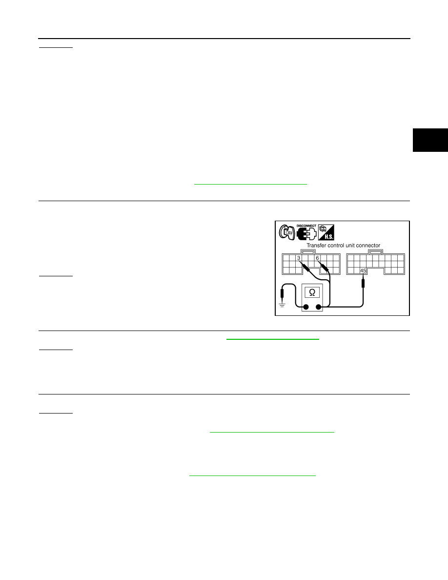
CHECK GROUND CIRCUIT
1. Turn ignition switch “OFF”. (Stay for at least 5 seconds.)
2. Disconnect transfer control unit harness connector.
3. Check continuity between transfer control unit harness connec-
tor M152 terminals 3, 6, M153 terminal 45 and ground.
Also check harness for short to power.
OK or NG
OK
>> GO TO 3.
NG
>> Repair open circuit or short to power in harness or con-
nectors.
3.
CHECK TRANSFER CONTROL UNIT
Check transfer control unit input/output signal. Refer to
OK or NG
OK
>> GO TO 4.
NG
>> Check transfer control unit pin terminals for damage or loose connection with harness connector.
If any items are damaged, repair or replace damaged parts.
4.
CHECK DTC
Perform the self-diagnosis, after driving a vehicle for a while.
OK or NG
OK
>> Inspection End.
NG
>> Replace transfer control unit. Refer to
DLN-140, "Removal and Installation"
Component Inspection
INFOID:0000000007357359
1. Turn ignition switch OFF. (Stay for at least 5 seconds.)
2. Remove transfer shut off relay. Refer to
DLN-19, "Component Parts Location"
.
Continuity should exist.
SDIA2691E
August 2012
2012 Pathfinder
DLN-30
< DTC/CIRCUIT DIAGNOSIS >
[TRANSFER: ATX14B]
P1811 POWER SUPPLY CIRCUIT FOR TRANSFER CONTROL UNIT
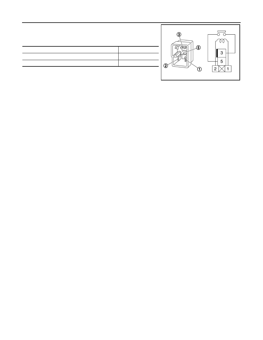
3. Apply 12V direct current between transfer shut off relay termi-
nals 1 and 2.
4. Check continuity between relay terminals 3 and 5.
5. If inspection results are abnormal replace the transfer shut off
relay.
Condition
Continuity
12V direct current supply between terminals 1 and 2
Yes
OFF
No
SCIA1245E
August 2012
2012 Pathfinder
P1802 – P1804, P1809 TRANSFER CONTROL UNIT
DLN-31
< DTC/CIRCUIT DIAGNOSIS >
[TRANSFER: ATX14B]
C
E
F
G
H
I
J
K
L
M
A
B
DLN
N
O
P
P1802 – P1804, P1809 TRANSFER CONTROL UNIT
Description
INFOID:0000000007357360
The transfer control unit controls the transfer control device which controls shifts between AUTO, 4H and 4LO
and between 2WD and 4WD. A DTC may set when any of the following occur:
• Malfunction is detected in the memory (RAM) system of transfer control unit.
• Malfunction is detected in the memory (ROM) system of transfer control unit.
• Malfunction is detected in the memory (EEPROM) system of transfer control unit.
• AD converter system of transfer control unit is malfunctioning.
DTC Logic
INFOID:0000000007357361
DTC DETECTION LOGIC
DTC CONFIRMATION PROCEDURE
1.
DTC CONFIRMATION PROCEDURE
1. Turn ignition switch ON.
2. Perform self-diagnosis.
Are DTCs P1802 - P1804 or P1809 detected?
YES
>> Perform diagnosis procedure. Refer to
.
NO
>> Inspection End.
Diagnosis Procedure
INFOID:0000000007357362
1.
INSPECTION START
Do you have CONSULT?
YES or NO
YES
>> GO TO 2.
NO
>> GO TO 3.
2.
PERFORM SELF-DIAGNOSIS (WITH CONSULT)
With CONSULT
1. Turn ignition switch ON. (Do not start engine.)
2. Select SELF-DIAG RESULTS mode for ALL MODE AWD/4WD with CONSULT.
3. Touch ERASE.
4. Turn ignition switch OFF and wait at least 10 seconds.
5. Perform the self-diagnosis again.
Is the CONTROL UNIT 1 [P1802], CONTROL UNIT 2 [P1803], CONTROL UNIT 3 [P1804] or CONTROL
UNIT 4 [P1809] displayed?
YES
>> Replace transfer control unit. Refer to
DLN-140, "Removal and Installation"
NO
>> Inspection End.
3.
PERFORM SELF-DIAGNOSIS (WITHOUT CONSULT)
DTC
CONSULT
Diagnostic item is detected when...
Reference
[P1802]
CONTROL UNIT 1
Malfunction is detected in the memory
(RAM) system of transfer control unit.
[P1803]
CONTROL UNIT 2
Malfunction is detected in the memory
(ROM) system of transfer control unit.
[P1804]
CONTROL UNIT 3
Malfunction is detected in the memory
(EEPROM) system of transfer control
unit.
[P1809]
CONTROL UNIT 4
AD converter system of transfer control
unit is malfunctioning.
August 2012
2012 Pathfinder

DLN-32
< DTC/CIRCUIT DIAGNOSIS >
[TRANSFER: ATX14B]
P1802 – P1804, P1809 TRANSFER CONTROL UNIT
Without CONSULT
1. Perform the self-diagnosis and then erase self-diagnostic results. Refer to
.
2. Perform the self-diagnosis again.
Do the self-diagnostic results indicate AD converter?
YES
>> Replace transfer control unit.
NO
>> Inspection End.
August 2012
2012 Pathfinder
P1807 VEHICLE SPEED SENSOR (A/T)
DLN-33
< DTC/CIRCUIT DIAGNOSIS >
[TRANSFER: ATX14B]
C
E
F
G
H
I
J
K
L
M
A
B
DLN
N
O
P
P1807 VEHICLE SPEED SENSOR (A/T)
Description
INFOID:0000000007357363
The transmission control module (TCM) transmits the output shaft revolution signal via CAN communication to
Transfer control unit. DTC P1807 will set when a malfunction is detected in the output shaft revolution signal
or an improper signal is input while driving.
DTC Logic
INFOID:0000000007357364
DTC DETECTION LOGIC
DTC CONFIRMATION PROCEDURE
1.
DTC CONFIRMATION PROCEDURE
1. Turn ignition switch ON.
2. Perform self-diagnosis.
Is DTC P1807 detected?
YES
>> Perform diagnosis procedure. Refer to
.
NO
>> Inspection End.
Diagnosis Procedure
INFOID:0000000007357365
1.
CHECK DTC WITH TCM
Perform self-diagnosis with TCM. Refer to
TM-37, "CONSULT Function (TRANSMISSION)"
Is any malfunction detected by self-diagnosis?
YES
>> Check the malfunctioning system.
NO
>> GO TO 2.
2.
CHECK TRANSFER CONTROL UNIT
Check transfer control unit input/output signal. Refer to
Are the inspection results normal?
YES
>> GO TO 3.
NO
>> Check transfer control unit pin terminals for damage or loose connection with harness connector.
If any items are damaged, repair or replace damaged parts.
3.
CHECK DTC
Drive the vehicle and then perform self-diagnosis.
Are the inspection results normal?
YES
>> Inspection End.
NO
>> Perform self-diagnosis with TCM again.
DTC
CONSULT
Diagnostic item is detected when...
Reference
[P1807]
VHCL SPEED SEN·AT
• Malfunction is detected in output shaft
revolution signal that is output from
TCM through CAN communication.
• Improper signal is input while driving.
August 2012
2012 Pathfinder
DLN-34
< DTC/CIRCUIT DIAGNOSIS >
[TRANSFER: ATX14B]
P1808 VEHICLE SPEED SENSOR (ABS)
P1808 VEHICLE SPEED SENSOR (ABS)
Description
INFOID:0000000007357366
The ABS actuator and electric unit (control unit) transmits a vehicle speed signal via CAN communication to
the transfer control unit. DTC P1808 sets when a malfunction is detected in the vehicle speed signal that is
output from the ABS actuator and electric unit (control unit) or an improper signal is input while driving.
DTC Logic
INFOID:0000000007357367
DTC DETECTION LOGIC
DTC CONFIRMATION PROCEDURE
1.
DTC CONFIRMATION PROCEDURE
1. Turn ignition switch ON.
2. Perform self-diagnosis.
Is DTC P1808 displayed?
YES
>> Perform diagnosis procedure. Refer to
.
NO
>> Inspection End.
Diagnosis Procedure
INFOID:0000000007357368
1.
CHECK DTC WITH ABS ACTUATOR AND ELECTRIC UNIT (CONTROL UNIT)
Perform self-diagnosis with ABS actuator and electric unit (control unit). Refer to
.
Is any malfunction detected by self-diagnosis?
YES
>> Check the malfunctioning system.
NO
>> GO TO 2.
2.
CHECK TRANSFER CONTROL UNIT
Check transfer control unit input/output signal. Refer to
Are the inspection results normal?
YES
>> GO TO 3.
NO
>> Check transfer control unit pin terminals for damage or loose connection with harness connector.
If any items are damaged, repair or replace damaged parts.
3.
CHECK DTC
Perform the self-diagnosis, after driving a vehicle for a while.
Are the inspection results normal?
YES
>> Inspection End.
NO
>> Perform self-diagnosis with ABS actuator and electric unit (control unit) again.
DTC
CONSULT
Diagnostic item is detected when...
Reference
[P1808]
VHCL SPEED SEN·ABS
• Malfunction is detected in vehicle
speed signal that is output from ABS
actuator and electric unit (control unit)
through CAN communication.
• Improper signal is input while driving.
Refer to
.
August 2012
2012 Pathfinder
P1810 NEUTRAL-4LO SWITCH
DLN-35
< DTC/CIRCUIT DIAGNOSIS >
[TRANSFER: ATX14B]
C
E
F
G
H
I
J
K
L
M
A
B
DLN
N
O
P
P1810 NEUTRAL-4LO SWITCH
Description
INFOID:0000000007357369
The neutral-4LO switch detects that the transfer case is in neutral or 4LO range. DTC P1810 will set when an
improper signal from the neutral-4LO switch is input due to an open or short circuit.
DTC Logic
INFOID:0000000007357370
DTC DETECTION LOGIC
DTC CONFIRMATION PROCEDURE
1.
DTC CONFIRMATION PROCEDURE
1. Turn ignition switch ON.
2. Perform self-diagnosis.
Is DTC P1810 displayed?
YES
>> Perform diagnosis procedure. Refer to
.
NO
>> Inspection End.
Diagnosis Procedure
INFOID:0000000007357371
Regarding Wiring Diagram information, refer to
1.
CHECK 4LO POSITION SWITCH SIGNAL
With CONSULT
1. Start engine.
2. Select DATA MONITOR mode for ALL MODE AWD/4WD with CONSULT.
3. Read out the value of N POSI SW TF.
Without CONSULT
1. Start engine.
DTC
CONSULT
Diagnostic item is detected when...
Reference
[P1810]
4L POSI SW TF
Improper signal from neutral-4LO switch
is input due to open or short circuit.
Condition
Display value
• Vehicle stopped
• Engine running
• A/T selector lever N position
• Brake pedal depressed
4WD shift switch: 2WD,
AUTO or 4H
OFF
4WD shift switch: 4H to
4LO (While actuator mo-
tor is operating.)
OFF
→
ON
4WD shift switch: 4LO to
4H (While actuator motor
is operating.)
ON
→
OFF
4WD shift switch: 4LO
ON
August 2012
2012 Pathfinder
DLN-36
< DTC/CIRCUIT DIAGNOSIS >
[TRANSFER: ATX14B]
P1810 NEUTRAL-4LO SWITCH
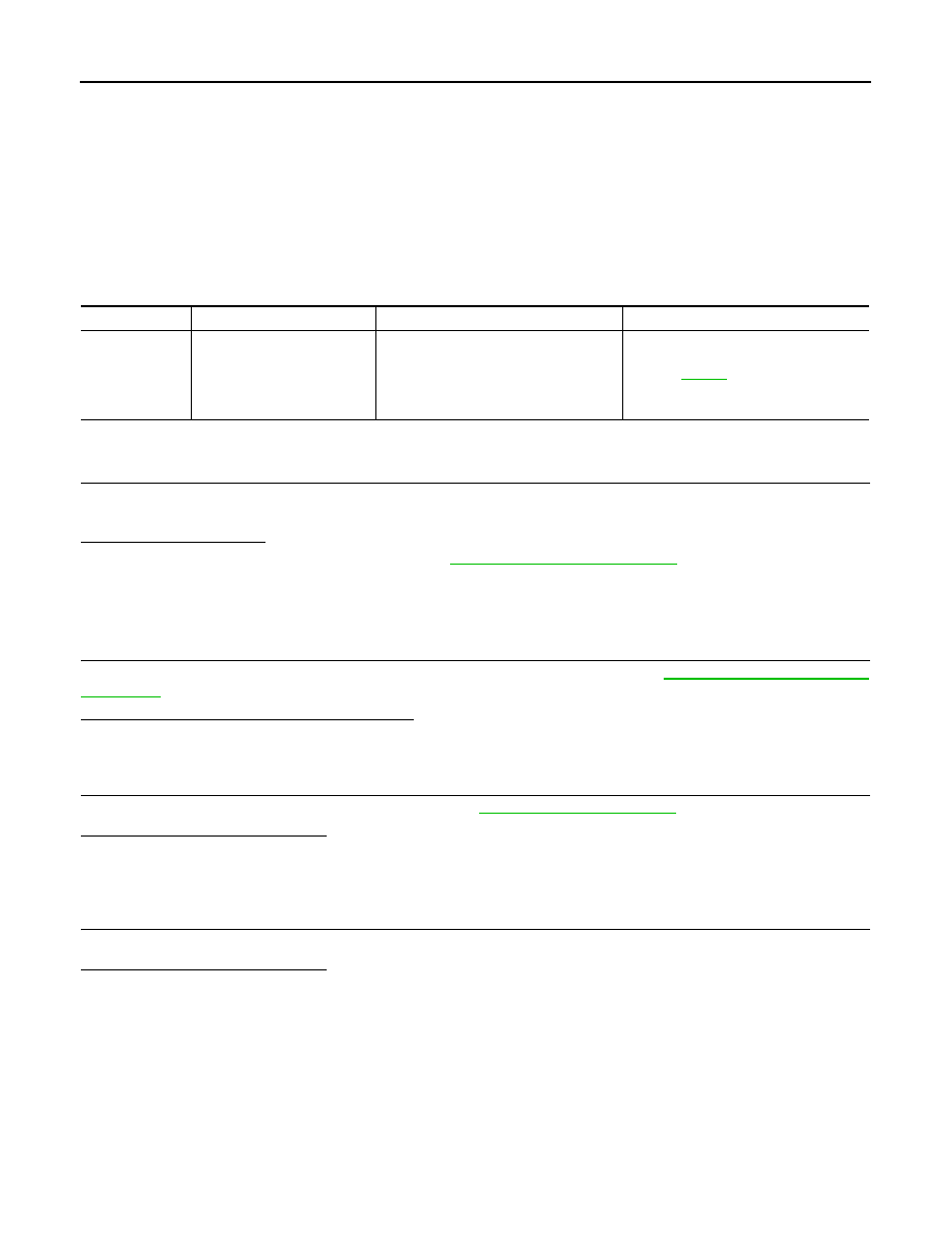
2. Check voltage between transfer control unit harness connector
terminal and ground.
Are inspection results normal?
YES
>> GO TO 5.
NO
>> GO TO 2.
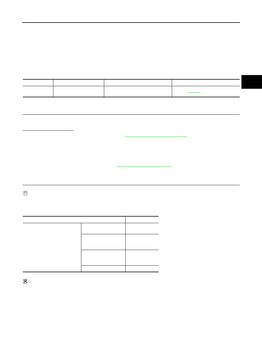
2.
CHECK HARNESS BETWEEN TRANSFER CONTROL UNIT AND NEUTRAL-4LO SWITCH
1. Turn ignition switch OFF. (Stay for at least 5 seconds.)
2. Disconnect transfer control unit harness connector and the neutral-4LO switch harness connector.
3. Check continuity between transfer control unit harness connec-
tor M153 terminal 25 and neutral-4LO switch harness connector
F60 terminal 13.
Also check harness for short to ground and short to power.
Are inspection results normal?
YES
>> GO TO 3.
NO
>> Repair or replace damaged parts.
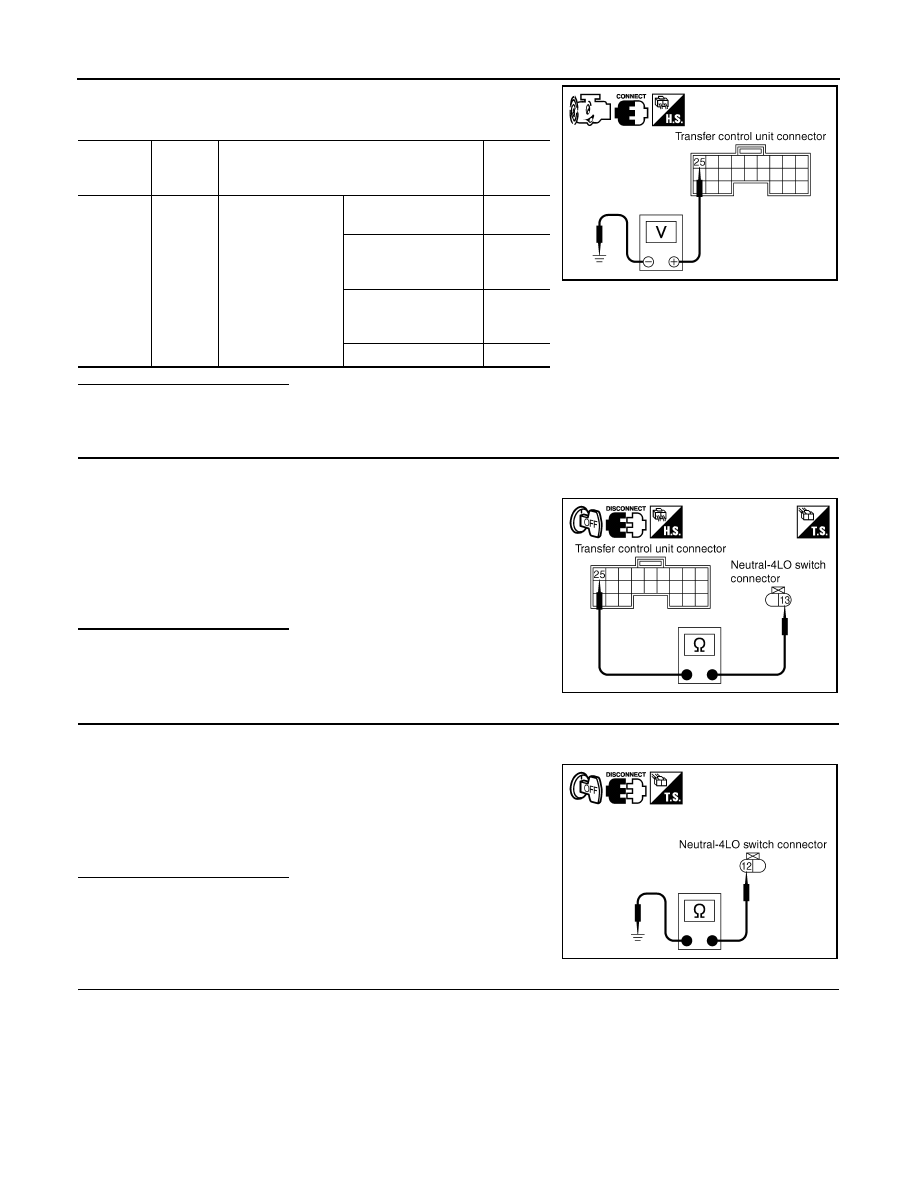
3.
CHECK GROUND CIRCUIT
1. Turn ignition switch OFF. (Stay for at least 5 seconds.)
2. Disconnect neutral-4LO switch harness connector.
3. Check continuity between neutral-4LO switch harness connec-
tor F60 terminal 12 and ground.
Also check harness for short to ground and short to power.
Are inspection results normal?
YES
>> GO TO 4.
NO
>> Repair open circuit or short to ground or short to power
in harness or connectors.
4.
CHECK 4LO SWITCH
1. Turn ignition switch OFF.
2. Disconnect neutral-4LO switch harness connector.
3. Remove neutral-4LO switch.
Connector
Terminal
(Wire col-
or)
Condition
Voltage
(Approx.)
M153
25 -
Ground
• Vehicle stopped
• Engine running
• A/T selector lever
N position
• Brake pedal de-
pressed
4WD shift switch:
2WD, AUTO or 4H
Battery
voltage
4WD shift switch: 4H to
4LO (While actuator
motor is operating.)
Battery
voltage
→
0V
4WD shift switch: 4LO
to 4H (While actuator
motor is operating.)
0V
→
Battery
voltage
4WD shift switch: 4LO
0V
SDIA2693E
Continuity should exist.
SDIA2694E
Continuity should exist.
SDIA2695E
August 2012
2012 Pathfinder
Нет комментариевНе стесняйтесь поделиться с нами вашим ценным мнением.
Текст