Nissan Pathfinder (2012 year). Instruction — part 360
EX-4
< PREPARATION >
PREPARATION
PREPARATION
PREPARATION
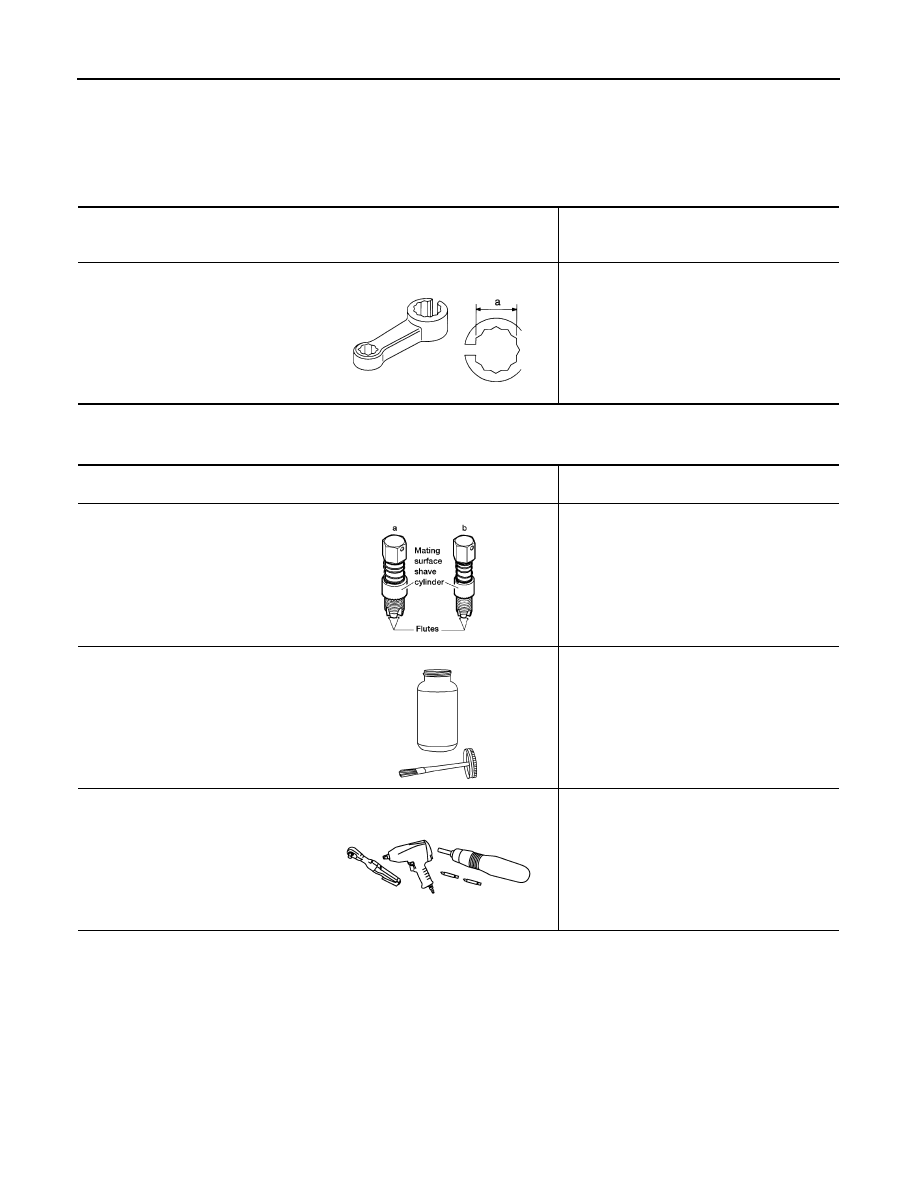
Special Service Tool
INFOID:0000000007358892
The actual shapes of Kent-Moore tools may differ from those of special service tools illustrated here.
Commercial Service Tool
INFOID:0000000007358893
Tool number
(Kent-Moore No.)
Tool name
Description
KV10114400
(J-38365)
Heated oxygen sensor wrench
Loosening or tightening heated oxygen sen-
sors:
a: 22 mm (0.87 in)
S-NT636
(Kent-Moore No.)
Tool name
Description
(J-43897-18)
(J-43897-12)
Oxygen sensor thread cleaner
Reconditioning the exhaust system threads
before installing a new heated oxygen sensor
(Use with anti-seize lubricant shown below):
a: J-43897-18 (18 mm, 0.71 in) diameter for
zirconia oxygen sensor
b: J-43897-12 (12 mm, 0.47 in) diameter for
titania oxygen sensor
Anti-seize lubricant (Permatex 133AR
or equivalent meeting MIL specifica-
tion MIL-A-907)
Lubricating oxygen sensor thread cleaning
tool when reconditioning exhaust system
threads
Power tool
Loosening nuts, screws and bolts
AEM488
AEM489
PIIB1407E
August 2012
2012 Pathfinder
EXHAUST SYSTEM
EX-5
< PERIODIC MAINTENANCE >
C
D
E
F
G
H
I
J
K
L
M
A
EX
N
P
O
PERIODIC MAINTENANCE
EXHAUST SYSTEM
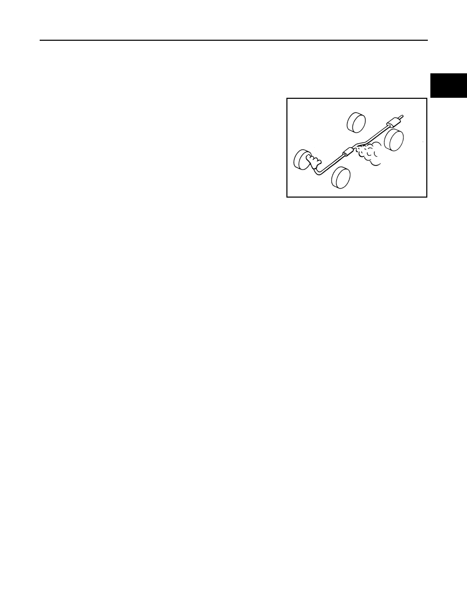
Checking Exhaust System
INFOID:0000000007358894
Check exhaust pipes, muffler and mounting for improper attachment,
leaks, cracks, damage or deterioration. Repair or replace as neces-
sary.
SMA211A
August 2012
2012 Pathfinder
EX-6
< REMOVAL AND INSTALLATION >
EXHAUST SYSTEM
REMOVAL AND INSTALLATION
EXHAUST SYSTEM
Exploded View
INFOID:0000000007358895
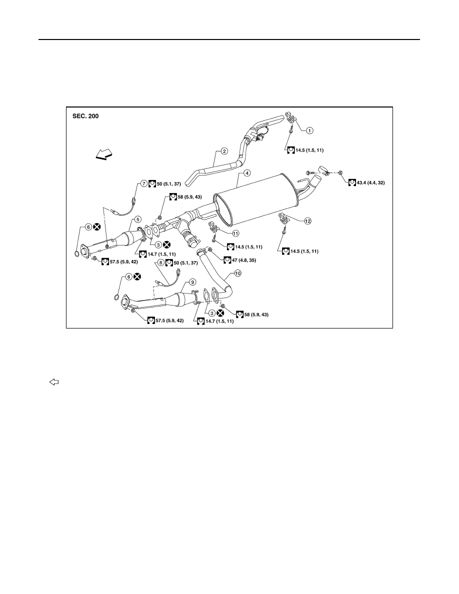
VQ40DE Exhaust System
AWBIA0855GB
1.
Tailpipe hanger bracket
2.
Tailpipe
3.
Gasket
4.
Main muffler
5.
Right front exhaust tube
6.
Ring gasket
7.
Heated oxygen sensor 2 (bank 1)
8.
Heated oxygen sensor 2 (bank 2)
9.
Left front exhaust tube
10. Center exhaust tube
11. Muffler hanger bracket front
12. Muffler hanger bracket rear
Front
August 2012
2012 Pathfinder
EXHAUST SYSTEM
EX-7
< REMOVAL AND INSTALLATION >
C
D
E
F
G
H
I
J
K
L
M
A
EX
N
P
O
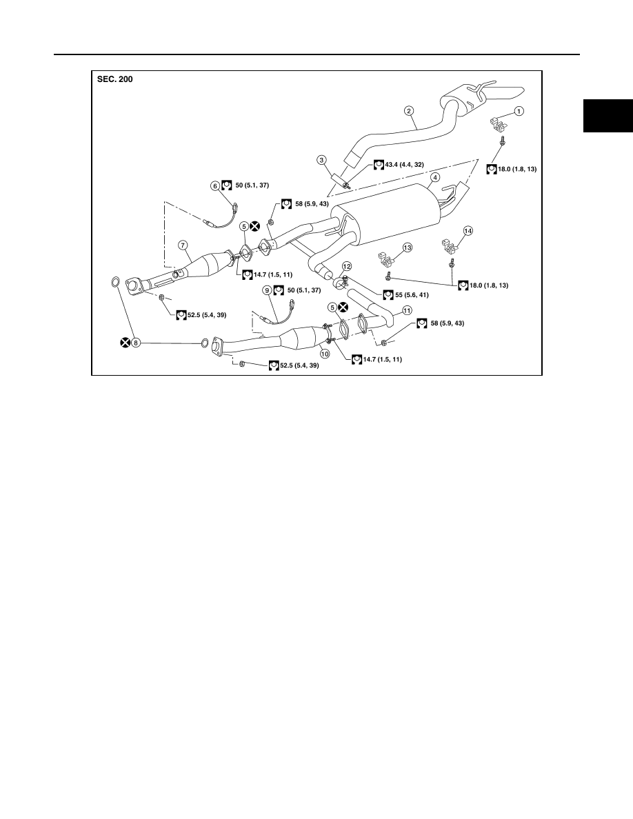
VK56DE Exhaust System
Removal and Installation
INFOID:0000000007358896
WARNING:
• Perform the operation with the exhaust system fully cooled. The system will be hot just after the
engine stops.
• Be careful not to cut your hand on the heat insulator edge.
CAUTION:
• Be sure to use genuine exhaust system parts or equivalents which are specially designed for heat
resistance, corrosion resistance, and shape.
REMOVAL
Remove exhaust system components using power tool.
• Remove heated oxygen sensor using Tool as needed.
INSTALLATION
Installation is in the reverse order of removal.
CAUTION:
• Always replace exhaust gaskets with new ones when reassembling.
• Before installing a new heated oxygen sensor, clean and lube the exhaust tube threads using suit-
able tool.
AWBIA0080GB
1.
Tailpipe hanger bracket
2.
Tailpipe
3.
Clamp
4.
Main muffler
5.
Gasket
6.
Heated oxygen sensor 2 (bank 2)
7.
Right front exhaust tube
8.
Ring gasket
9.
Heated oxygen sensor 2 (bank 1)
10. Left front exhaust tube
11. Center exhaust tube
12. Clamp
13. Muffler hanger bracket front
14. Muffler hanger bracket rear
Tool number
: KV10114400 (J-38365)
Oxygen sensor thread cleaner
: — (J-43897-18)
Oxygen sensor thread cleaner
: — (J-43897-12)
August 2012
2012 Pathfinder
EX-8
< REMOVAL AND INSTALLATION >
EXHAUST SYSTEM
• Discard any heated oxygen sensor which has been dropped from a height of more than 0.5 m (19.7
in) onto a hard surface such as a concrete floor; install a new one.
• Do not over-tighten the heated oxygen sensor. Doing so may damage the heated oxygen sensor,
resulting in the MIL coming on.
• If any mounting insulator is badly deformed, repair or replace it. If deposits such as mud pile up on
the mounting insulators, clean and inspect them.
• Temporarily tighten the nuts on the exhaust manifold side and the bolts on the vehicle side. Check
each part for interference with other components, and then tighten the nuts and bolts to specifica-
tion.
INSPECTION AFTER INSTALLATION
• With the engine running, check exhaust tube joints for exhaust gas leaks and unusual noises.
• Check to ensure that mounting brackets and mounting rubbers are installed properly and free from undue
stress. Improper installation could result in excessive noise and vibration.
August 2012
2012 Pathfinder
EXL-1
DRIVER CONTROLS
C
D
E
F
G
H
I
J
K
M
SECTION
EXL
A
B
EXL
N
O
P
CONTENTS
EXTERIOR LIGHTING SYSTEM
BASIC INSPECTION . . . . . . . . .
DIAGNOSIS AND REPAIR WORKFLOW . . ..
Work Flow . . . . . . . . . . . . . . . .....
SYSTEM DESCRIPTION . . . . . . . ..
HEADLAMP . . . . . . . . . . . . . . .
System Diagram . . . . . . . . . . . . . ....
System Description . . . . . . . . . . . . ...
Component Parts Location . . . . . . . . . ....
Component Description . . . . . . . . . . .....
DAYTIME RUNNING LIGHT SYSTEM . . . ...
System Diagram . . . . . . . . . . . . . ....
System Description . . . . . . . . . . . . ...
Component Parts Location . . . . . . . . . ..
Component Description . . . . . . . . . . ...
AUTO LIGHT SYSTEM . . . . . . . . . ..
System Diagram . . . . . . . . . . . . . ..
System Description . . . . . . . . . . . . .
Component Parts Location . . . . . . . . . ..
Component Description . . . . . . . . . . ...
FRONT FOG LAMP . . . . . . . . . . .
System Diagram . . . . . . . . . . . . . ..
System Description . . . . . . . . . . . . .
Component Parts Location . . . . . . . . . ..
Component Description . . . . . . . . . . ...
TURN SIGNAL AND HAZARD WARNING
LAMPS . . . . . . . . . . . . . . . ...
System Diagram . . . . . . . . . . . . . ..
System Description . . . . . . . . . . . . .
Component Parts Location . . . . . . . . . ..
Component Description . . . . . . . . . . ...
PARKING, LICENSE PLATE AND TAIL
LAMPS . . . . . . . . . . . . . . . ...
System Diagram . . . . . . . . . . . . . ..
System Description . . . . . . . . . . . . .
Component Parts Location . . . . . . . . . ..
Component Description . . . . . . . . . . ...
COMBINATION SWITCH READING SYSTEM
...
System Diagram . . . . . . . . . . . . . ..
System Description . . . . . . . . . . . . ..
Component Parts Location . . . . . . . . . ..
TRAILER TOW . . . . . . . . . . . . ..
System Diagram . . . . . . . . . . . . . ..
System Description . . . . . . . . . . . . ..
Component Parts Location . . . . . . . . . ..
Component Description . . . . . . . . . . ...
DIAGNOSIS SYSTEM (BCM) . . . . . . ...
COMMON ITEM . . . . . . . . . . . . . . .
COMMON ITEM : CONSULT Function (BCM -
COMMON ITEM) . . . . . . . . . . . . . .
HEADLAMP . . . . . . . . . . . . . . . ...
HEADLAMP : CONSULT Function (BCM - HEAD
LAMP) . . . . . . . . . . . . . . . . . ..
FLASHER . . . . . . . . . . . . . . . . ...
FLASHER : CONSULT Function (BCM - FLASH-
ER) . . . . . . . . . . . . . . . . . . ..
COMB SW . . . . . . . . . . . . . . . . ..
COMB SW : CONSULT Function (BCM - COMB
SW) . . . . . . . . . . . . . . . . . . ..
DIAGNOSIS SYSTEM (IPDM E/R) . . . . ...
Diagnosis Description . . . . . . . . . . . ..
CONSULT Function (IPDM E/R) . . . . . . . .
DTC/CIRCUIT DIAGNOSIS . . . . . . .
POWER SUPPLY AND GROUND CIRCUIT .
BCM (BODY CONTROL MODULE) . . . . . . ..
August 2012
2012 Pathfinder
EXL-2
BCM (BODY CONTROL MODULE) : Diagnosis
Procedure . . . . . . . . . . . . . . . ...
IPDM E/R (INTELLIGENT POWER DISTRIBU-
TION MODULE ENGINE ROOM) . . . . . . . .
HEADLAMP (HI) CIRCUIT . . . . . . . .
Description . . . . . . . . . . . . . . . ..
Component Function Check . . . . . . . . ...
Diagnosis Procedure . . . . . . . . . . . ..
HEADLAMP (LO) CIRCUIT . . . . . . . ...
Description . . . . . . . . . . . . . . . ..
Component Function Check . . . . . . . . ...
Diagnosis Procedure . . . . . . . . . . . ..
Component Inspection . . . . . . . . . . ....
DAYTIME LIGHT RELAY CIRCUIT . . . . ...
Description . . . . . . . . . . . . . . . ..
Diagnosis Procedure . . . . . . . . . . . ..
Component Inspection . . . . . . . . . . ....
FRONT FOG LAMP CIRCUIT . . . . . . ...
Description . . . . . . . . . . . . . . . ..
Component Function Check . . . . . . . . ...
Diagnosis Procedure . . . . . . . . . . . ..
PARKING LAMP CIRCUIT . . . . . . . .
Description . . . . . . . . . . . . . . . ..
Component Function Check . . . . . . . . ...
Diagnosis Procedure . . . . . . . . . . . ..
TURN SIGNAL LAMP CIRCUIT . . . . . .
Description . . . . . . . . . . . . . . . ..
Component Function Check . . . . . . . . ...
Diagnosis Procedure . . . . . . . . . . . ..
OPTICAL SENSOR . . . . . . . . . . ...
Description . . . . . . . . . . . . . . . ..
Component Function Check . . . . . . . . ...
Diagnosis Procedure . . . . . . . . . . . ..
ECU DIAGNOSIS INFORMATION . . . ..
BCM (BODY CONTROL MODULE) . . . . ..
Reference Value . . . . . . . . . . . . . .
Terminal Layout . . . . . . . . . . . . . ..
Physical Values . . . . . . . . . . . . . ..
Fail Safe . . . . . . . . . . . . . . . . .
DTC Inspection Priority Chart . . . . . . . ..
DTC Index . . . . . . . . . . . . . . . ..
IPDM E/R (INTELLIGENT POWER DISTRI-
BUTION MODULE ENGINE ROOM) . . . . .
Reference Value . . . . . . . . . . . . . .
Terminal Layout . . . . . . . . . . . . . ..
Physical Values . . . . . . . . . . . . . ..
Fail Safe . . . . . . . . . . . . . . . . .
DTC Index . . . . . . . . . . . . . . . ..
WIRING DIAGRAM . . . . . . . . .
HEADLAMP . . . . . . . . . . . . . ...
Wiring Diagram . . . . . . . . . . . . . ...
DAYTIME LIGHT SYSTEM . . . . . . . ...
Wiring Diagram . . . . . . . . . . . . . ...
AUTO LIGHT SYSTEM . . . . . . . . . .
Wiring Diagram . . . . . . . . . . . . . ...
FRONT FOG LAMP SYSTEM . . . . . . ...
Wiring Diagram . . . . . . . . . . . . . ...
TURN SIGNAL AND HAZARD WARNING
LAMP SYSTEM . . . . . . . . . . . .
Wiring Diagram . . . . . . . . . . . . . .
PARKING, LICENSE PLATE AND TAIL
LAMPS SYSTEM . . . . . . . . . . . ..
Wiring Diagram . . . . . . . . . . . . . .
STOP LAMP . . . . . . . . . . . . . .
Wiring Diagram . . . . . . . . . . . . . .
BACK-UP LAMP . . . . . . . . . . . ..
Wiring Diagram . . . . . . . . . . . . . .
TRAILER TOW . . . . . . . . . . . . .
Wiring Diagram . . . . . . . . . . . . . .
SYMPTOM DIAGNOSIS . . . . . . ...
EXTERIOR LIGHTING SYSTEM SYMPTOMS ..
Symptom Table . . . . . . . . . . . . . .
NORMAL OPERATING CONDITION . . . ...
Description . . . . . . . . . . . . . . .
BOTH SIDE HEADLAMPS DO NOT SWITCH
TO HIGH BEAM . . . . . . . . . . . .
Description . . . . . . . . . . . . . . .
Diagnosis Procedure . . . . . . . . . . . .
DAYTIME LIGHT SYSTEM INOPERATIVE . .
Description . . . . . . . . . . . . . . .
Diagnosis Procedure . . . . . . . . . . . .
BOTH SIDE HEADLAMPS (LO) ARE NOT
TURNED ON . . . . . . . . . . . . . .
Description . . . . . . . . . . . . . . .
Diagnosis Procedure . . . . . . . . . . . .
PARKING, LICENSE PLATE AND TAIL
LAMPS ARE NOT TURNED ON . . . . . ..
Description . . . . . . . . . . . . . . .
Diagnosis Procedure . . . . . . . . . . . .
BOTH SIDE FRONT FOG LAMPS ARE NOT
TURNED ON . . . . . . . . . . . . . .
Description . . . . . . . . . . . . . . .
August 2012
2012 Pathfinder
EXL-3
C
D
E
F
G
H
I
J
K
M
A
B
EXL
N
O
P
Diagnosis Procedure . . . . . . . . . . . .
PRECAUTION . . . . . . . . . . .
PRECAUTIONS . . . . . . . . . . . .
Precaution Necessary for Steering Wheel Rota-
tion After Battery Disconnect . . . . . . . . .
Precaution for Work . . . . . . . . . . . ..
PERIODIC MAINTENANCE . . . . . ...
ADJUSTMENT AND INSPECTION . . . . ..
HEADLAMP . . . . . . . . . . . . . . . .
HEADLAMP : Aiming Adjustment . . . . . . .
FRONT FOG LAMP . . . . . . . . . . . . .
FRONT FOG LAMP : Aiming Adjustment . . . .
UNIT REMOVAL AND INSTALLATION .
HEADLAMP . . . . . . . . . . . . . ..
Bulb Replacement . . . . . . . . . . . . .
Removal and Installation . . . . . . . . . ...
Disassembly and Assembly . . . . . . . . ..
OPTICAL SENSOR . . . . . . . . . . ..
Removal and Installation . . . . . . . . . ...
FRONT FOG LAMP . . . . . . . . . .
Bulb Replacement . . . . . . . . . . . . .
Removal and Installation . . . . . . . . . ...
LIGHTING & TURN SIGNAL SWITCH . . ...
Removal and Installation . . . . . . . . . ...
HAZARD SWITCH . . . . . . . . . . ..
Removal and Installation . . . . . . . . . ...
HIGH-MOUNTED STOP LAMP . . . . . ..
High-Mounted Stop Lamp . . . . . . . . . ..
LICENSE PLATE LAMP . . . . . . . . .
Bulb Replacement . . . . . . . . . . . . .
Removal and Installation . . . . . . . . . ...
REAR COMBINATION LAMP . . . . . . .
Bulb Replacement . . . . . . . . . . . . .
Removal and Installation . . . . . . . . . ...
SERVICE DATA AND SPECIFICATIONS
(SDS) . . . . . . . . . . . . . . ..
BULB SPECIFICATIONS . . . . . . . .
Headlamp . . . . . . . . . . . . . . . ..
Exterior Lamp . . . . . . . . . . . . . .
August 2012
2012 Pathfinder
Нет комментариевНе стесняйтесь поделиться с нами вашим ценным мнением.
Текст