Nissan Pathfinder (2012 year). Instruction — part 85
FRONT DISC BRAKE
BR-7
< BASIC INSPECTION >
C
D
E
G
H
I
J
K
L
M
A
B
BR
N
O
P
BASIC INSPECTION
FRONT DISC BRAKE
BRAKE PAD
BRAKE PAD : Inspection
INFOID:0000000007356603
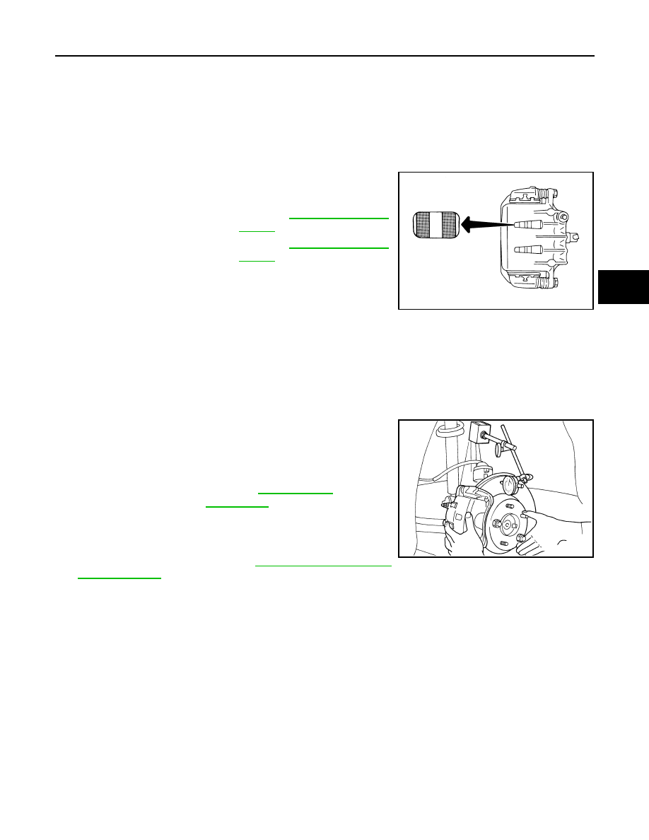
PAD WEAR
Check pad thickness from the inspection holes on cylinder body.
Check using a scale if necessary.
DISC ROTOR
DISC ROTOR : Inspection
INFOID:0000000007356604
VISUAL
Check surface of disc rotor for uneven wear, cracks, and serious damage. Replace as necessary.
RUNOUT
1. Attach disc rotor to wheel hub using wheel nuts at two or more
positions.
2. Inspect runout using a dial gauge placed at 10 mm (0.39 in)
inside the disc edge.
NOTE:
Before measuring, make sure that wheel bearing axial end play
is within the specification. Refer to
.
3. When runout exceeds limit value, displace mounting positions of disc rotor by one hole. And then find a
position of the minimum value for runout.
4. If runout is outside the specified value after performing the above operation, turn disc rotor using Tool.
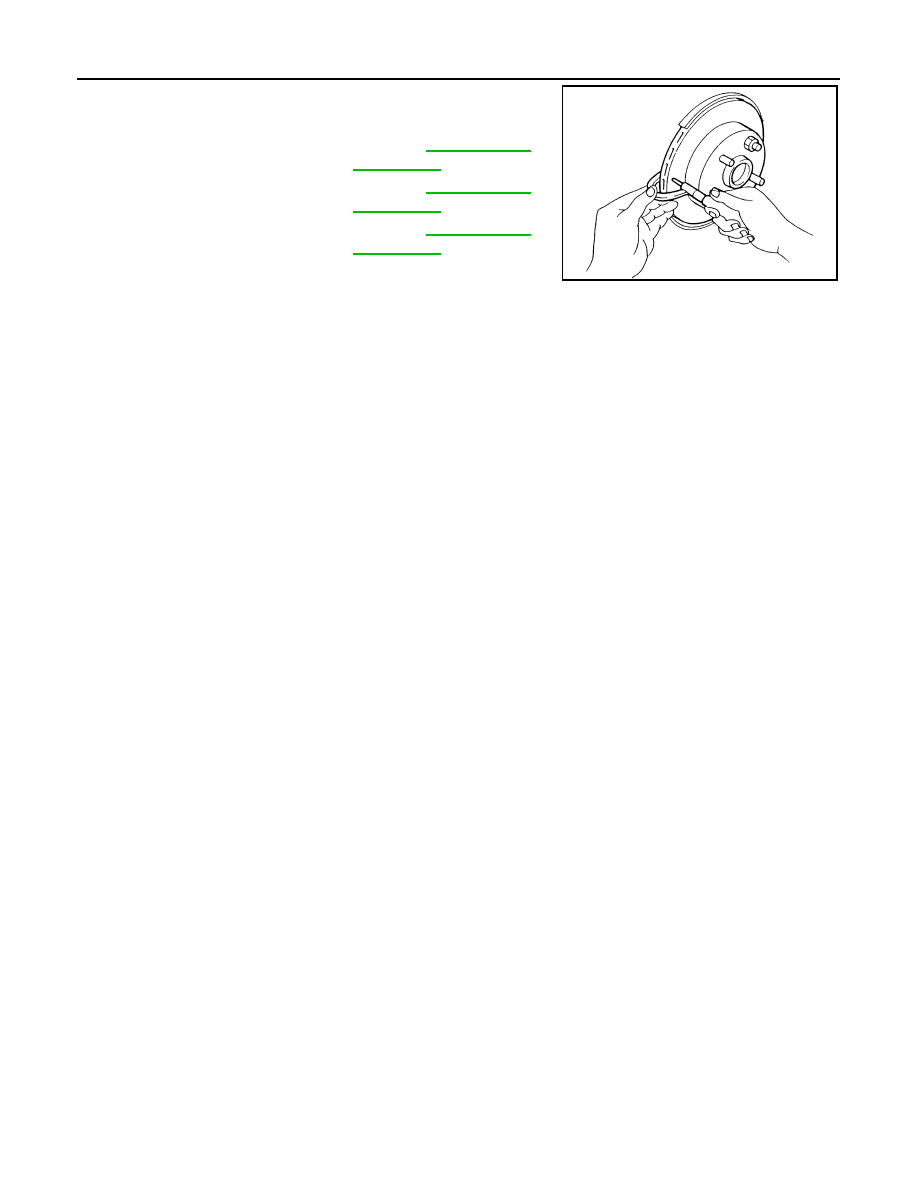
THICKNESS
Standard thickness (new) : Refer to
.
Repair limit thickness
: Refer to
.
WFIA0522E
Runout limit
: Refer to
(with it attached to the vehicle)
Tool number
: 38-PFM90.5 ( — )
BRA0580D
August 2012
2012 Pathfinder
BR-8
< BASIC INSPECTION >
FRONT DISC BRAKE
Check thickness of the disc rotor using a micrometer. Replace disc
rotor if thickness is less then the repair limit thickness.
Standard thickness (new)
: Refer to
.
Repair limit thickness
: Refer to
.
Maximum uneven wear
(measured at 8 positions)
: Refer to
.
SBR020B
August 2012
2012 Pathfinder
REAR DISC BRAKE
BR-9
< BASIC INSPECTION >
C
D
E
G
H
I
J
K
L
M
A
B
BR
N
O
P
REAR DISC BRAKE
BRAKE PAD
BRAKE PAD : Inspection
INFOID:0000000007356605
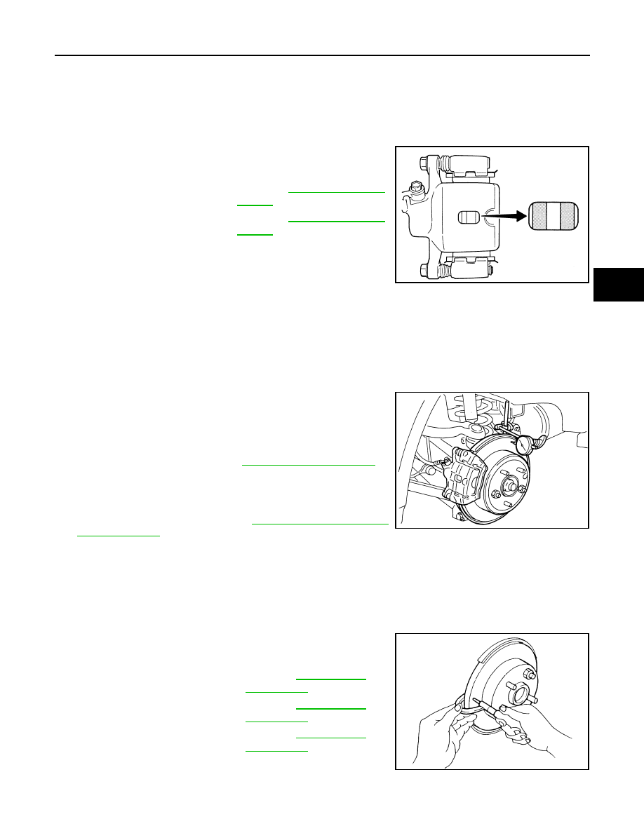
PAD WEAR
Check pad thickness from an inspection hole on cylinder body.
Check using a scale if necessary.
DISC ROTOR
DISC ROTOR : Inspection
INFOID:0000000007356606
VISUAL
Check surface of disc rotor for uneven wear, cracks, and serious damage. Replace as necessary.
RUNOUT
1. Attach disc rotor to wheel hub using wheel nuts at two or more
positions.
2. Inspect runout using dial gauge placed at 10 mm (0.39 in) inside
disc edge.
NOTE:
Before measuring, make sure that wheel bearing axial end play
is within the specification. Refer to
.
3. When runout exceeds limit value, displace mounting positions of disc rotor by one hole. And then find a
position of the minimum value for runout.
4. If runout is outside the specified value after performing the above operation, turn disc rotor using Tool.
THICKNESS
Check the thickness of the disc rotor using a micrometer. Replace
disc rotor if the thickness is less then the repair limit thickness.
Standard thickness (new) : Refer to
Repair limit thickness
: Refer to
BRA0010D
Runout limit
: Refer to
(with it attached to the vehicle)
Tool number
: 38-PFM90.5 ( — )
BRA0697D
Standard thickness (new)
: Refer to
.
Repair limit thickness
: Refer to
.
Maximum uneven wear
(measured at 8 positions)
: Refer to
.
SFIA2284E
August 2012
2012 Pathfinder
BR-10
< BASIC INSPECTION >
BRAKE BOOSTER
BRAKE BOOSTER
Inspection
INFOID:0000000007356607
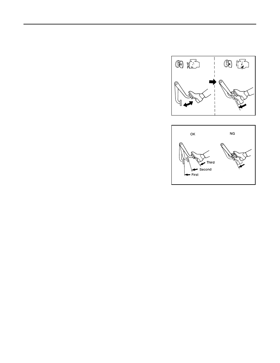
OPERATION
With engine stopped, change vacuum to atmospheric pressure by
depressing brake pedal several times. Then with brake pedal fully
depressed, start engine and when vacuum pressure reaches the
standard, make sure that clearance between brake pedal and floor
panel decreases.
AIR TIGHT
• Run engine at idle for approximately 1 minute, and stop it after
applying vacuum to booster. Depress brake pedal normally to
change vacuum to atmospheric pressure. Make sure that distance
at intervals of 5 seconds between brake pedal and floor panel
gradually increases.
• Depress brake pedal while engine is running, and stop engine with pedal depressed. The pedal stroke
should not change after holding pedal down for 30 seconds.
BRA0037D
SBR365AA
August 2012
2012 Pathfinder
VACUUM LINES
BR-11
< BASIC INSPECTION >
C
D
E
G
H
I
J
K
L
M
A
B
BR
N
O
P
VACUUM LINES
Inspection
INFOID:0000000007356608
VISUAL INSPECTION
Check for improper assembly, damage and deterioration. Replace as necessary.
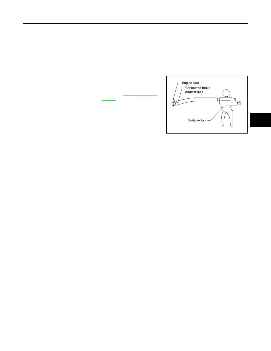
CHECK VALVE INSPECTION
Airtightness Inspection
Use a suitable tool to check vacuum check valve. Connect to brake
booster side of check valve.
Check valve specification
: Refer to
.
LFIA0217E
August 2012
2012 Pathfinder
BR-12
< BASIC INSPECTION >
BRAKE MASTER CYLINDER
BRAKE MASTER CYLINDER
On Board Inspection
INFOID:0000000007356609
LEAK INSPECTION
Check for leaks at master cylinder to brake booster attachment point, reservoir tank, and brake tube connec-
tions.
August 2012
2012 Pathfinder
BRAKE TUBE AND HOSE
BR-13
< BASIC INSPECTION >
C
D
E
G
H
I
J
K
L
M
A
B
BR
N
O
P
BRAKE TUBE AND HOSE
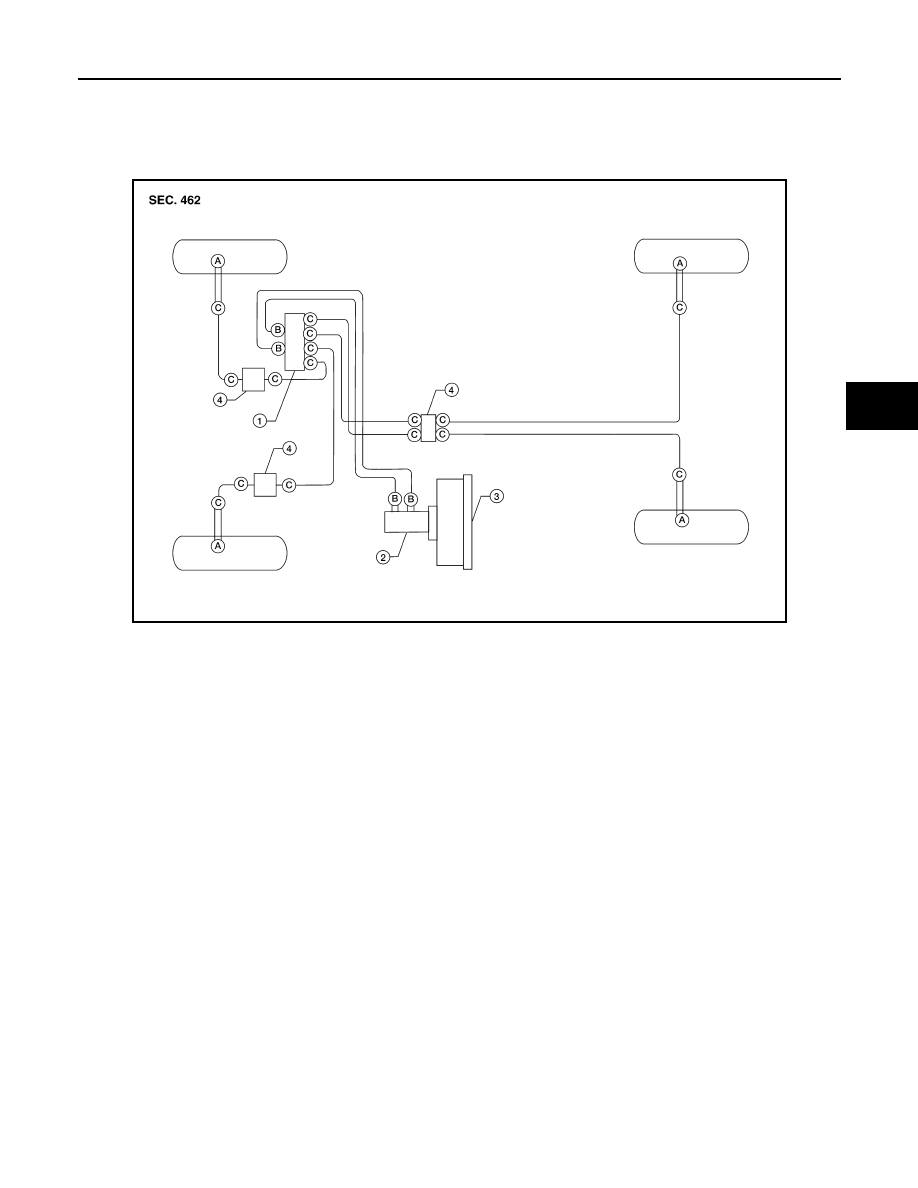
Hydraulic Circuit
INFOID:0000000007356610
Brake Tube and Hose Connections
AWFIA0411ZZ
1.
Actuator
2.
Master cylinder
3.
Brake booster
4.
Connector
A.
Union bolt
18.2 N·m (1.9 kg-m, 13 ft-lb)
B.
Flare nut M12
18.2 N·m (1.9 kg-m, 13 ft-lb)
C.
Flare nut M10
13.0 N·m (1.3 kg-m, 10 ft-lb)
August 2012
2012 Pathfinder
BR-14
< BASIC INSPECTION >
BRAKE TUBE AND HOSE
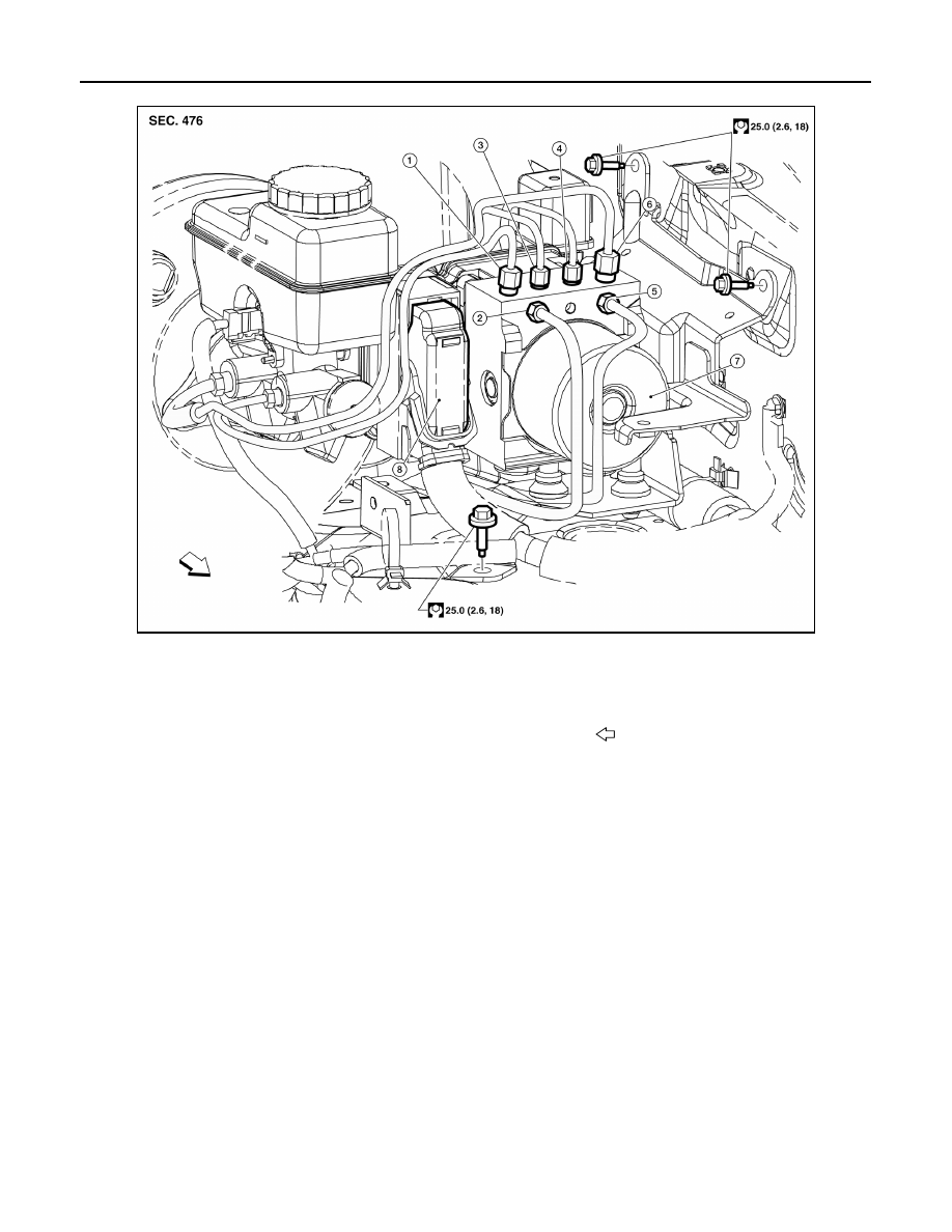
ABS Actuator and Electric Unit Brake Pipe Connections for VQ40DE
AWFIA0743GB
1.
From the master cylinder secondary side
18.2 N·m (1.9 kg-m, 13 ft-lb)
2.
To rear right disc brake
13.0 N·m (1.3 kg-m, 10 ft-lb)
3.
To rear left disc brake
13.0 N·m (1.3 kg-m, 10 ft-lb)
4.
To front right disc brake
13.0 N·m (1.3 kg-m, 10 ft-lb)
5.
To front left disc brake
13.0 N·m (1.3 kg-m, 10 ft-lb)
6.
From the master cylinder primary side
18.2 N·m (1.9 kg-m, 13 ft-lb)
7.
ABS actuator and electric unit (control unit) 8.
Harness connector
Front
August 2012
2012 Pathfinder
Нет комментариевНе стесняйтесь поделиться с нами вашим ценным мнением.
Текст