Nissan Pathfinder (2012 year). Instruction — part 83

BCS-44
< ECU DIAGNOSIS INFORMATION >
BCM (BODY CONTROL MODULE)
DTC Index
INFOID:0000000007354948
NOTE:
Details of time display
• CRNT: Displays when there is a malfunction now or after returning to the normal condition until turning igni-
tion switch OFF
→
ON again.
• 1 - 39: Displayed if any previous malfunction is present when current condition is normal. It increases like 1
→
2
→
3...38
→
39 after returning to the normal condition whenever ignition switch OFF
→
ON. The counter
remains at 39 even if the number of cycles exceeds it. It is counted from 1 again when turning ignition switch
OFF
→
ON after returning to the normal condition if the malfunction is detected again.
Priority
DTC
1
• U1000: CAN COMM CIRCUIT
2
• B2190: NATS ANTENNA AMP
• B2191: DIFFERENCE OF KEY
• B2192: ID DISCORD BCM-ECM
• B2193: CHAIN OF BCM-ECM
• B2013: STRG COMM 1
• B2552: INTELLIGENT KEY
• B2590: NATS MALFUNCTION
3
• C1729: VHCL SPEED SIG ERR
• C1735: IGNITION SIGNAL
4
• C1704: LOW PRESSURE FL
• C1705: LOW PRESSURE FR
• C1706: LOW PRESSURE RR
• C1707: LOW PRESSURE RL
• C1708: [NO DATA] FL
• C1709: [NO DATA] FR
• C1710: [NO DATA] RR
• C1711: [NO DATA] RL
• C1712: [CHECKSUM ERR] FL
• C1713: [CHECKSUM ERR] FR
• C1714: [CHECKSUM ERR] RR
• C1715: [CHECKSUM ERR] RL
• C1716: [PRESSDATA ERR] FL
• C1717: [PRESSDATA ERR] FR
• C1718: [PRESSDATA ERR] RR
• C1719: [PRESSDATA ERR] RL
• C1720: [CODE ERR] FL
• C1721: [CODE ERR] FR
• C1722: [CODE ERR] RR
• C1723: [CODE ERR] RL
• C1724: [BATT VOLT LOW] FL
• C1725: [BATT VOLT LOW] FR
• C1726: [BATT VOLT LOW] RR
• C1727: [BATT VOLT LOW] RL
CONSULT display
Fail-safe
Intelligent Key
warning lamp ON
Low tire pressure
warning lamp ON
Reference page
No DTC is detected.
Further testing may be required.
—
—
—
—
U1000: CAN COMM CIRCUIT
X
—
—
B2013: STRG COMM 1
—
—
—
B2190: NATS ANTENNA AMP
—
—
—
(with I-Key)
(without I-
Key)
B2191: DIFFERENCE OF KEY
—
—
—
(with I-Key)
(without I-
Key)
August 2012
2012 Pathfinder

BCS
BCM (BODY CONTROL MODULE)
BCS-45
< ECU DIAGNOSIS INFORMATION >
C
D
E
F
G
H
I
J
K
L
B
A
O
P
N
B2192: ID DISCORD BCM-ECM
—
—
—
(with I-Key)
(without I-
Key)
B2193: CHAIN OF BCM-ECM
—
—
—
(with I-Key)
(without I-
Key)
B2552: INTELLIGENT KEY
—
—
—
B2590: NATS MALFUNCTION
—
—
—
C1708: [NO DATA] FL
—
—
X
C1709: [NO DATA] FR
—
—
X
C1710: [NO DATA] RR
—
—
X
C1711: [NO DATA] RL
—
—
X
C1712: [CHECKSUM ERR] FL
—
—
X
C1713: [CHECKSUM ERR] FR
—
—
X
C1714: [CHECKSUM ERR] RR
—
—
X
C1715: [CHECKSUM ERR] RL
—
—
X
C1716: [PRESSDATA ERR] FL
—
—
X
C1717: [PRESSDATA ERR] FR
—
—
X
C1718: [PRESSDATA ERR] RR
—
—
X
C1719: [PRESSDATA ERR] RL
—
—
X
C1720: [CODE ERR] FL
—
—
X
C1721: [CODE ERR] FR
—
—
X
C1722: [CODE ERR] RR
—
—
X
C1723: [CODE ERR] RL
—
—
X
C1724: [BATT VOLT LOW] FL
—
—
X
C1725: [BATT VOLT LOW] FR
—
—
X
C1726: [BATT VOLT LOW] RR
—
—
X
C1727: [BATT VOLT LOW] RL
—
—
X
C1729: VHCL SPEED SIG ERR
—
—
X
C1735: IGNITION SWITCH
—
—
X
CONSULT display
Fail-safe
Intelligent Key
warning lamp ON
Low tire pressure
warning lamp ON
Reference page
August 2012
2012 Pathfinder
BCS-46
< WIRING DIAGRAM >
BCM (BODY CONTROL MODULE)
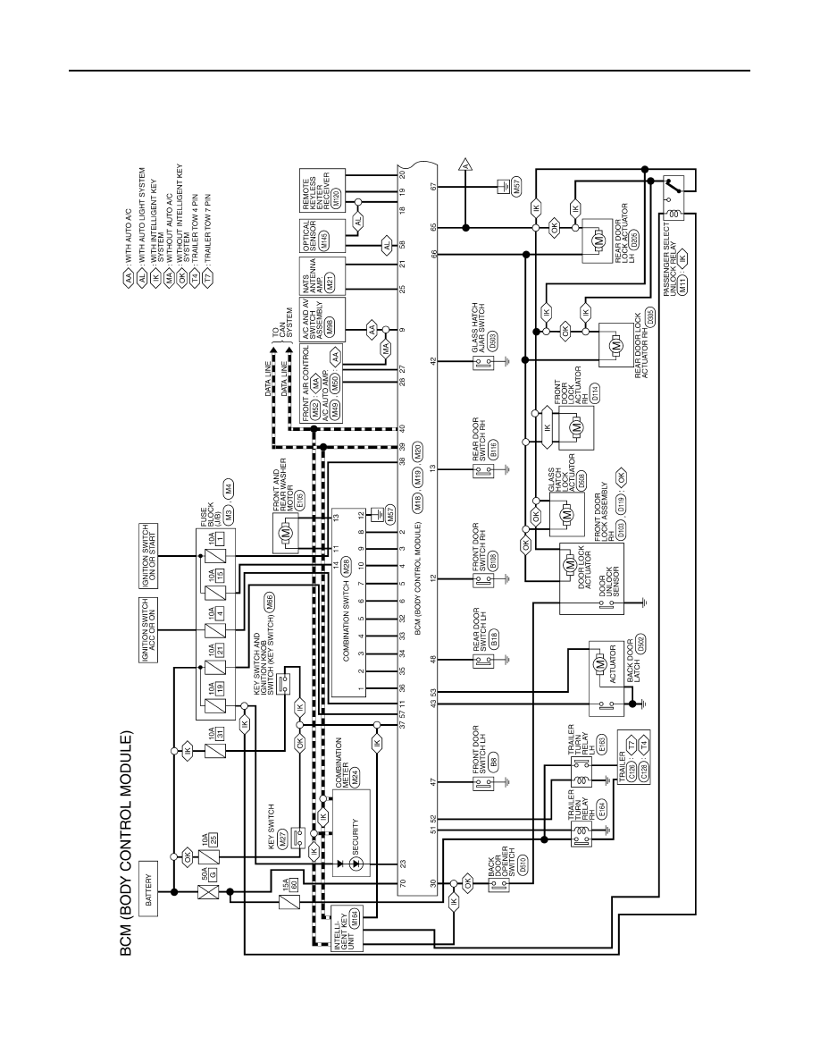
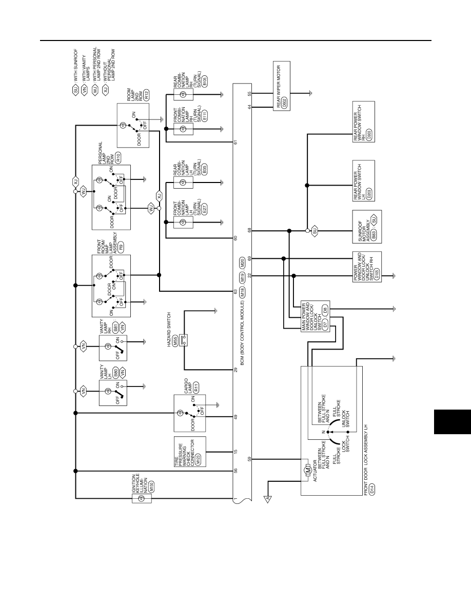
WIRING DIAGRAM
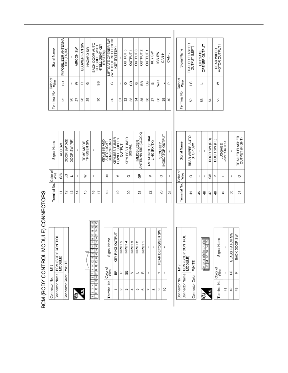
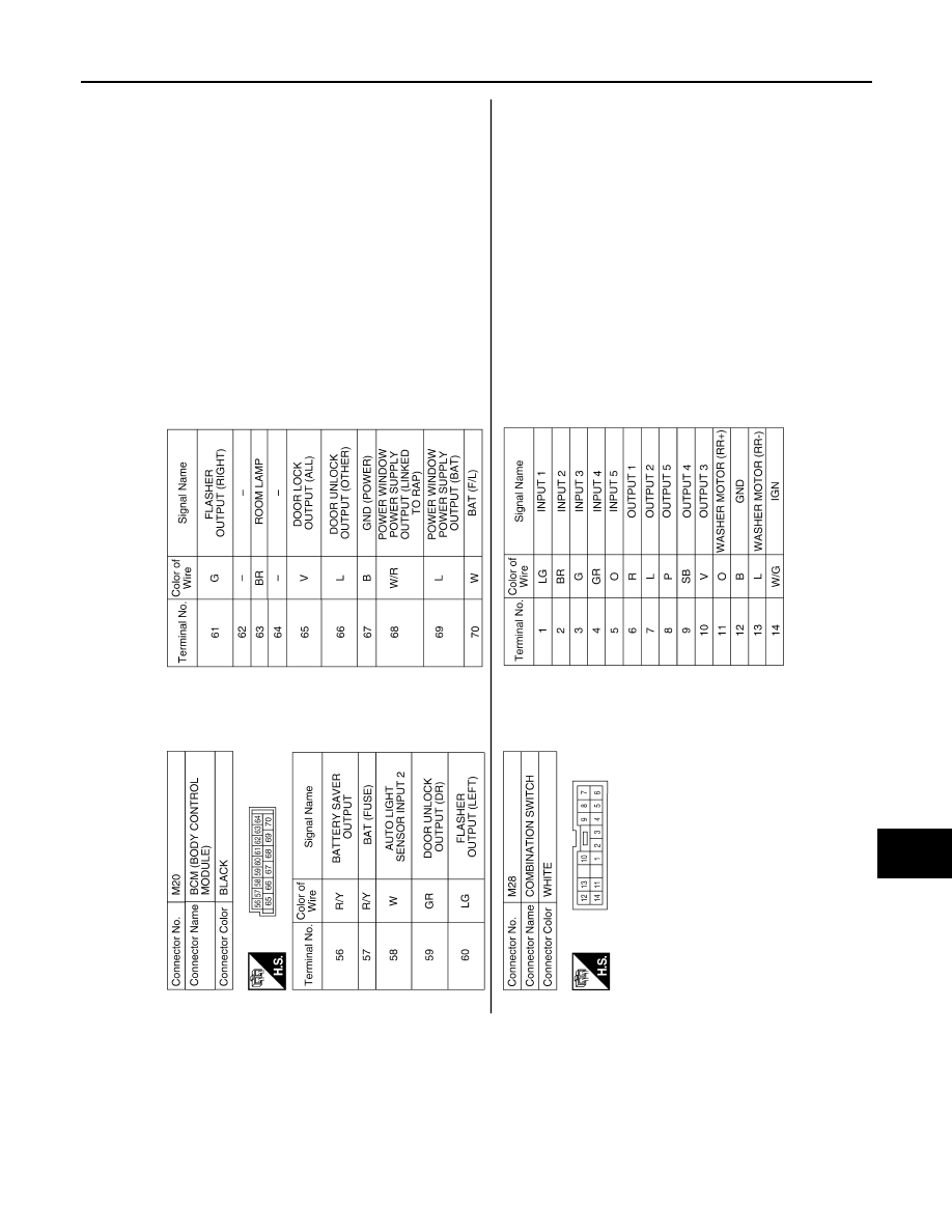
BCM (BODY CONTROL MODULE)
Wiring Diagram
INFOID:0000000007354949
ABMWA1415GB
August 2012
2012 Pathfinder
BCS
BCM (BODY CONTROL MODULE)
BCS-47
< WIRING DIAGRAM >
C
D
E
F
G
H
I
J
K
L
B
A
O
P
N
ABMWA1416GB
August 2012
2012 Pathfinder
BCS-48
< WIRING DIAGRAM >
BCM (BODY CONTROL MODULE)
ABMIA3465GB
August 2012
2012 Pathfinder
BCS
BCM (BODY CONTROL MODULE)
BCS-49
< WIRING DIAGRAM >
C
D
E
F
G
H
I
J
K
L
B
A
O
P
N
ABMIA3466GB
August 2012
2012 Pathfinder

BCS-50
< SYMPTOM DIAGNOSIS >
COMBINATION SWITCH SYSTEM SYMPTOMS
SYMPTOM DIAGNOSIS
COMBINATION SWITCH SYSTEM SYMPTOMS
Symptom Table
INFOID:0000000007354950
1. Perform the data monitor of CONSULT to check for any malfunctioning item.
2. Check the malfunction combinations.
Malfunction item:
×
3. Identify the malfunctioning part from the agreed combination and repair or replace the part.
Malfunction combi-
nation
Data monitor item
TURN SIGNAL R
T
U
R
N
SIGNAL L
HI BEAM
SW
HEADLAMP SW
1
HEADLAMP SW
2
TA
IL LAM
P
SW
P
ASSING SW
AUT
O
LI
GHT
SW
FR FOG SW
FR WIPE
R HI
F
R
WIPER LOW
FR
W
IP
E
R
I
N
T
FR W
ASHER S
W
IN
T V
O
LU
ME
RR W
IPER ON
R
R
WIPER
IN
T
RR W
ASHER SW
A
×
×
×
×
B
×
×
×
×
C
×
×
×
×
D
×
×
×
×
E
×
×
×
F
×
×
×
G
×
×
×
×
H
×
×
×
I
×
×
×
×
J
×
×
×
×
K
All Items
L
If only one item is detected or the item is not applicable to the combinations A to L
Malfunction
combination
Malfunctioning part
Repair or replace
A
Combination switch INPUT 1 circuit
Inspect the combination switch input circuit applicable to the malfunctioning
part. Refer to
B
Combination switch INPUT 2 circuit
C
Combination switch INPUT 3 circuit
D
Combination switch INPUT 4 circuit
E
Combination switch INPUT 5 circuit
F
Combination switch OUTPUT 1 circuit
Inspect the combination switch output circuit applicable to the malfunction-
ing part. Refer to
.
G
Combination switch OUTPUT 2 circuit
H
Combination switch OUTPUT 3 circuit
I
Combination switch OUTPUT 4 circuit
J
Combination switch OUTPUT 5 circuit
K
BCM
Replace BCM. Refer to
BCS-53, "Removal and Installation"
.
L
Light and turn signal switch or front wip-
er and washer switch
Replace the switch that cannot be operated.
August 2012
2012 Pathfinder
BCS
PRECAUTIONS
BCS-51
< PRECAUTION >
C
D
E
F
G
H
I
J
K
L
B
A
O
P
N
PRECAUTION
PRECAUTIONS
Precaution for Supplemental Restraint System (SRS) "AIR BAG" and "SEAT BELT
PRE-TENSIONER"
INFOID:0000000007354951
The Supplemental Restraint System such as “AIR BAG” and “SEAT BELT PRE-TENSIONER”, used along
with a front seat belt, helps to reduce the risk or severity of injury to the driver and front passenger for certain
types of collision. This system includes seat belt switch inputs and dual stage front air bag modules. The SRS
system uses the seat belt switches to determine the front air bag deployment, and may only deploy one front
air bag, depending on the severity of a collision and whether the front occupants are belted or unbelted.
Information necessary to service the system safely is included in the SR and SB section of this Service Man-
ual.
WARNING:
• To avoid rendering the SRS inoperative, which could increase the risk of personal injury or death in
the event of a collision which would result in air bag inflation, all maintenance must be performed by
an authorized NISSAN/INFINITI dealer.
• Improper maintenance, including incorrect removal and installation of the SRS, can lead to personal
injury caused by unintentional activation of the system. For removal of Spiral Cable and Air Bag
Module, see the SR section.
• Do not use electrical test equipment on any circuit related to the SRS unless instructed to in this
Instruction. SRS wiring harnesses can be identified by yellow and/or orange harnesses or har-
ness connectors.
PRECAUTIONS WHEN USING POWER TOOLS (AIR OR ELECTRIC) AND HAMMERS
WARNING:
• When working near the Airbag Diagnosis Sensor Unit or other Airbag System sensors with the Igni-
tion ON or engine running, DO NOT use air or electric power tools or strike near the sensor(s) with a
hammer. Heavy vibration could activate the sensor(s) and deploy the air bag(s), possibly causing
serious injury.
• When using air or electric power tools or hammers, always switch the Ignition OFF, disconnect the
battery, and wait at least 3 minutes before performing any service.
Precaution Necessary for Steering Wheel Rotation After Battery Disconnect
INFOID:0000000007354952
NOTE:
• This Procedure is applied only to models with Intelligent Key system and NATS (NISSAN ANTI-THEFT SYS-
TEM).
• Remove and install all control units after disconnecting both battery cables with the ignition knob in the
″
LOCK
″
position.
• Always use CONSULT to perform self-diagnosis as a part of each function inspection after finishing work. If
DTC is detected, perform trouble diagnosis according to self-diagnostic results.
For models equipped with the Intelligent Key system and NATS, an electrically controlled steering lock mech-
anism is adopted on the key cylinder.
For this reason, if the battery is disconnected or if the battery is discharged, the steering wheel will lock and
steering wheel rotation will become impossible.
If steering wheel rotation is required when battery power is interrupted, follow the procedure below before
starting the repair operation.
OPERATION PROCEDURE
1. Connect both battery cables.
NOTE:
Supply power using jumper cables if battery is discharged.
2. Use the Intelligent Key or mechanical key to turn the ignition switch to the
″
ACC
″
position. At this time, the
steering lock will be released.
3. Disconnect both battery cables. The steering lock will remain released and the steering wheel can be
rotated.
4. Perform the necessary repair operation.
August 2012
2012 Pathfinder
Нет комментариевНе стесняйтесь поделиться с нами вашим ценным мнением.
Текст