Nissan Sentra. Instruction — part 451

COMPONENT PARTS
EXL-7
< SYSTEM DESCRIPTION >
C
D
E
F
G
H
I
J
K
M
A
B
EXL
N
O
P
Component Description
INFOID:0000000009757470
1.
IPDM E/R, (Headlamp high relay,
Headlamp low relay, Taillamp relay
and Front fog lamp relay (if equipped))
2.
Stop lamp switch
3.
Parking brake switch
4.
Combination meter
5.
Combination switch
(lighting and turn signal switch)
6.
BCM (view with combination meter re-
moved)
7.
Optical sensor
8.
Front door switch LH (Other doors
similar)
9.
Hazard switch
10. Daytime light relay (if equipped)
Part
Description
BCM
Controls the exterior lighting system.
Combination switch
(Lighting & turn signal switch)
BCS-9, "COMBINATION SWITCH READING SYSTEM : System Description"
(with Intelligent
Key system) or
BCS-80, "COMBINATION SWITCH READING SYSTEM : System Description"
(with-
out Intelligent Key system).
IPDM E/R
Controls the integrated relays and supplies voltage to the load according to the request from the BCM
via CAN communication.
Stop lamp switch
Transmits power when the brake pedal is pressed to operate stop lamps.
Combination meter
Refer to
MWI-8, "METER SYSTEM : System Description"
.
Daytime light relay
(if equipped)
Sends power to the daytime lamp when operated by the IPDM E/R.
Front door switch LH/RH
Transmits the door open signal to the BCM.
Rear door switch LH/RH
Optical sensor
Optical sensor converts the outside brightness (lux) to voltage and transmits the optical sensor signal
to BCM to operate the autolight system.
Parking brake switch
Transmits the parking brake switch signal to the combination meter to operate the autolight system.
Hazard switch
Inputs the hazard switch signal to BCM.
EXL-8
< SYSTEM DESCRIPTION >
SYSTEM
SYSTEM
HEADLAMP SYSTEM
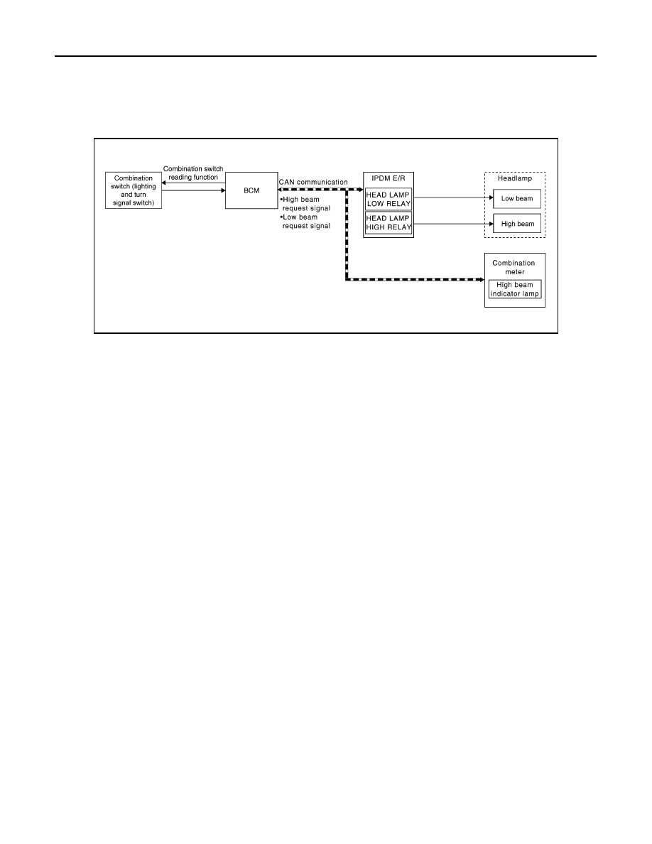
HEADLAMP SYSTEM : System Diagram
INFOID:0000000009757471
HEADLAMP SYSTEM : System Description
INFOID:0000000009757472
LOW BEAM OPERATION
When the lighting switch is in 2nd position, the BCM receives input requesting the headlamps to illuminate.
This input is communicated to the IPDM E/R across the CAN communication lines. The CPU of the IPDM E/R
controls the headlamp low relay coil which supplies power to the low beam headlamps.
HIGH BEAM OPERATION/FLASH-TO-PASS OPERATION
With the lighting switch in the 2nd position and placed in HIGH position, the BCM receives input requesting the
headlamp high beams to illuminate. The flash to pass feature can be used any time and also sends a signal to
the BCM. This input is communicated to the IPDM E/R across the CAN communication lines. The CPU of the
combination meter controls the ON/OFF status off the HIGH BEAM indicator. The CPU of the IPDM E/R con-
trols the headlamp high relay coil which supplies power to the high beam headlamps.
The combination meter receives a high beam request signal (ON) through the CAN communication lines and
turns the high beam indicator lamp ON.
EXTERIOR LAMP BATTERY SAVER CONTROL
With the combination switch (lighting and turn signal switch) in the 2nd position and the ignition switch is
turned from ON or ACC to OFF, the battery saver feature is activated.
Under this condition, the headlamps remain illuminated for a period of time, unless the lighting switch position
is changed. If the lighting switch position is changed, then the headlamps are turned off.
AUTO LIGHT SYSTEM
AWLIA1980GB
SYSTEM
EXL-9
< SYSTEM DESCRIPTION >
C
D
E
F
G
H
I
J
K
M
A
B
EXL
N
O
P
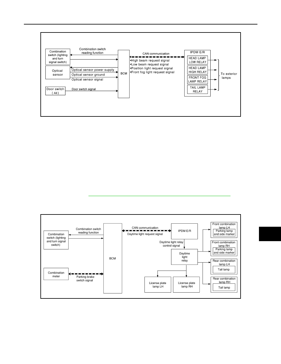
AUTO LIGHT SYSTEM : System Diagram
INFOID:0000000009757473
AUTO LIGHT SYSTEM : System Description
INFOID:0000000009757474
• BCM (Body Control Module) controls auto light operation according to signals from optical sensor, lighting
switch and ignition switch.
• IPDM E/R (Intelligent Power Distribution Module Engine Room) operates parking, license plate, tail, front fog
lamps and headlamps according to CAN communication signals from BCM.
• Optical sensor detects ambient brightness of 800 to 2,500 lux. And optical sensor converts light (lux) to volt-
age, then sends the optical sensor signal to BCM.
OUTLINE
The auto light control system has an optical sensor that detects outside brightness.
When the lighting switch is in AUTO position, it automatically turns ON/OFF the parking, license plate, tail,
front fog lamps and headlamps in accordance with the ambient light. Sensitivity can be adjusted. For the
details of the setting, Refer to
EXL-19, "HEADLAMP : CONSULT Function (BCM - HEAD LAMP)"
.
DAYTIME RUNNING LIGHT SYSTEM
DAYTIME RUNNING LIGHT SYSTEM : System Diagram
INFOID:0000000009757475
DAYTIME RUNNING LIGHT SYSTEM : System Description
INFOID:0000000009757476
System Description
The daytime light system is equipped with a daytime light control that activates the daytime lights when the
engine is operating. If the parking brake is applied, the daytime lights will turn OFF. The daytime lights will turn
ON when the parking brake is released.
AWLIA1981GB
AWLIA2058GB
EXL-10
< SYSTEM DESCRIPTION >
SYSTEM
OPERATION
The BCM monitors inputs from the parking brake switch and the combination switch (lighting and turn signal
switch) to determine when to operate the daytime light system. The BCM sends a daytime light request to the
IPDM E/R via the CAN communication lines. The IPDM E/R grounds the daytime light relay which in turn, pro-
vides power to the daytime lights.
FRONT FOG LAMP SYSTEM
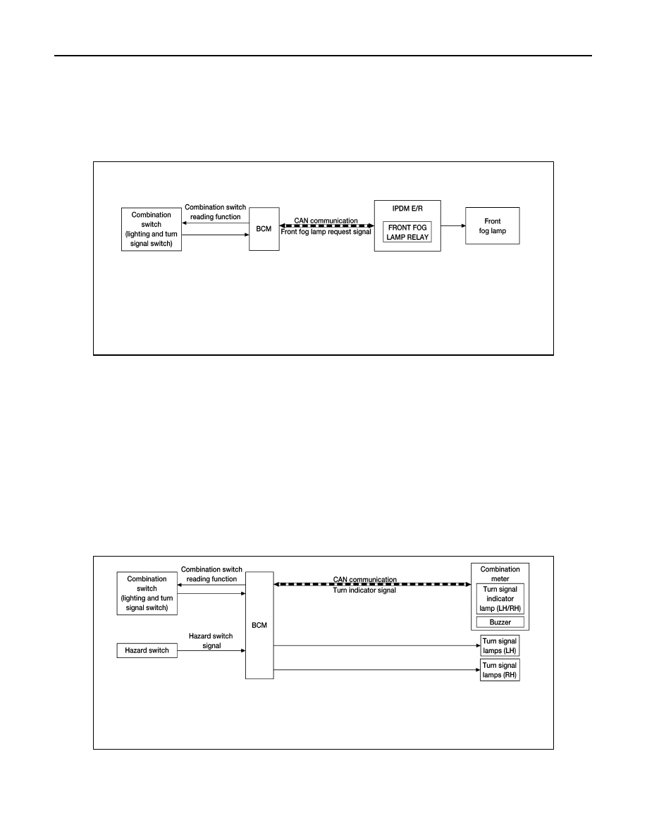
FRONT FOG LAMP SYSTEM : System Diagram
INFOID:0000000009757477
FRONT FOG LAMP SYSTEM : System Description
INFOID:0000000009757478
The front fog lamps are activated with the combination switch (lighting and turn signal switch). The lighting
switch signal to the BCM is monitored with the BCM combination switch reading function. When the fog lamps
are turned ON with the lighting switch, the BCM sends a front fog lamp request signal via CAN communication
lines to the IPDM E/R. The IPDM E/R grounds the front fog lamp relay coil to activate the front fog lamps.
FRONT FOG LAMP OPERATION
When the lighting switch is in front fog lamp ON position and also in 1st or 2nd position or AUTO position
(headlamp is ON), the BCM detects FR FOG ON and the HEAD LAMP 1, 2 ON or the AUTO LIGHT ON. The
BCM sends a front fog lamp request ON signal via the CAN communication lines to the IPDM E/R. The IPDM
E/R then turns ON the front fog lamp relay sending power to the front fog lamps.
TURN SIGNAL AND HAZARD WARNING LAMPS
TURN SIGNAL AND HAZARD WARNING LAMPS : System Diagram
INFOID:0000000009757479
TURN SIGNAL AND HAZARD WARNING LAMPS : System Description
INFOID:0000000009757480
TURN SIGNAL OPERATION
AWLIA1719GB
AWLIA1721GB
Нет комментариевНе стесняйтесь поделиться с нами вашим ценным мнением.
Текст