Nissan Sentra. Instruction — part 452
SYSTEM
EXL-11
< SYSTEM DESCRIPTION >
C
D
E
F
G
H
I
J
K
M
A
B
EXL
N
O
P
When the combination switch (lighting and turn signal switch) is in LH or RH turn position with the ignition
switch in the ON position, the BCM receives input requesting the turn RH or turn LH lamps to illuminate. The
BCM controls the turn signal power to the respective turn signal lamp. The BCM also sends a turn indicator
signal ON request via the CAN communication lines to the combination meter. The combination meter then
activates the appropriate turn signal indicator and audible buzzer.
HAZARD LAMP OPERATION
When the hazard switch is in the ON position, the BCM receives input requesting the hazard lamps illuminate.
The BCM controls the turn signal power to both the LH and RH turn signal lamps. The BCM sends a hazard
indicator signal ON request via the CAN communication lines to the combination meter. The combination
meter then activates both the LH and RH turn signal indicators and audible buzzer.
PARKING, LICENSE PLATE AND TAIL LAMPS
PARKING, LICENSE PLATE AND TAIL LAMPS : System Diagram
INFOID:0000000009757481
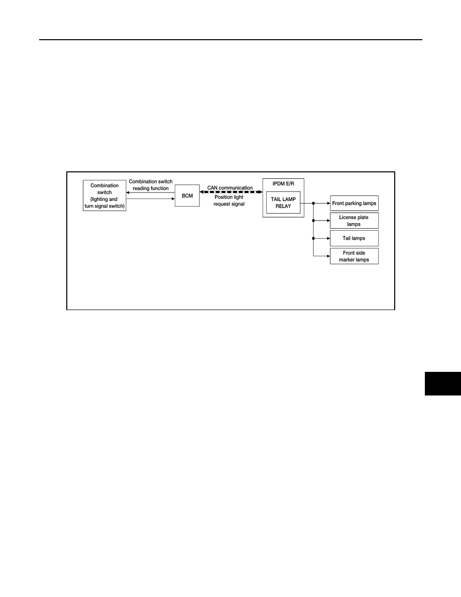
PARKING, LICENSE PLATE AND TAIL LAMPS : System Description
INFOID:0000000009757482
PARKING, LICENSE PLATE AND TAIL LAMPS OPERATION
When the lighting switch is in 1st or 2nd position, BCM detects the LIGHTING SWITCH 1st or 2nd POSITION
ON. The BCM sends a parking light ON request via the CAN communication lines to the IPDM E/R. The IPDM
E/R then activates the tail lamp relay which sends power to the parking and instrument illumination circuits.
EXTERIOR LAMP BATTERY SAVER CONTROL
With the combination switch (lighting and turn signal switch) in the 1st or 2nd position and the ignition switch is
turned from ON or ACC to OFF, the battery saver feature is activated.
Under this condition, the exterior lamps remain illuminated for a period of time unless the lighting switch posi-
tion is changed. If the lighting switch position is changed, then the exterior lamps are turned off.
COMBINATION SWITCH READING SYSTEM
COMBINATION SWITCH READING SYSTEM : System Diagram (With Intelligent Key
AWLIA1723GB
EXL-12
< SYSTEM DESCRIPTION >
SYSTEM
System)
INFOID:0000000010295730
COMBINATION SWITCH READING SYSTEM : System Description (With Intelligent
Key System)
INFOID:0000000010295731
OUTLINE
• BCM reads the status of the combination switch (light, turn signal, wiper and washer) and recognizes the
status of each switch.
• BCM has a combination of 5 output terminals (OUTPUT 1 - 5) and 5 input terminals (INPUT 1 - 5). It reads a
maximum of 20 switch states.
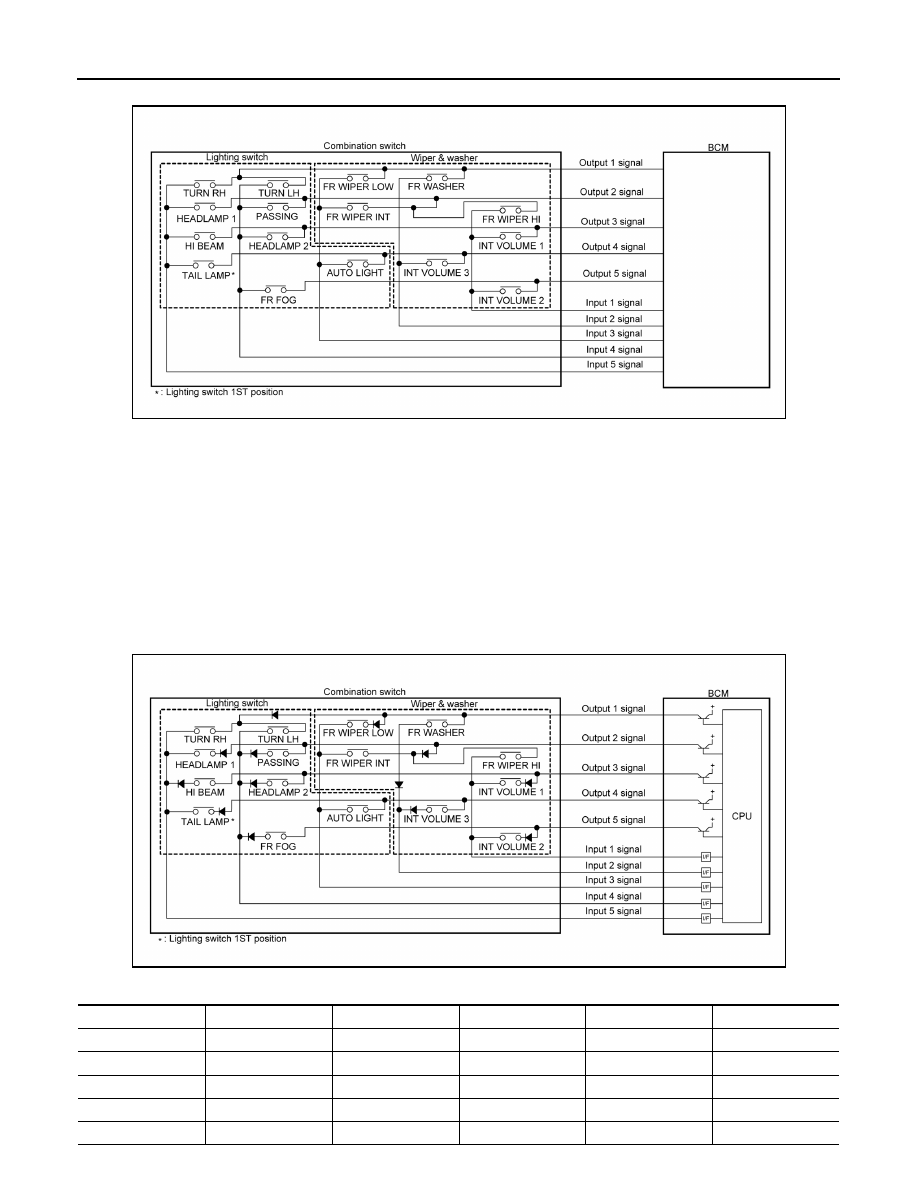
COMBINATION SWITCH MATRIX
Combination switch circuit
Combination switch INPUT-OUTPUT system list
AWMIA1359GB
System
INPUT 1
INPUT 2
INPUT 3
INPUT 4
INPUT 5
OUTPUT 1
—
FR WASHER
FR WIPER LOW
TURN LH
TURN RH
OUTPUT 2
FR WIPER HI
—
FR WIPER INT
PASSING
HEADLAMP 1
OUTPUT 3
INT VOLUME 1
—
—
HEADLAMP 2
HI BEAM
OUTPUT 4
—
INT VOLUME 3
AUTO LIGHT
—
TAIL LAMP
OUTPUT 5
INT VOLUME 2
—
—
FR FOG
—
AWMIA1360GB
SYSTEM
EXL-13
< SYSTEM DESCRIPTION >
C
D
E
F
G
H
I
J
K
M
A
B
EXL
N
O
P
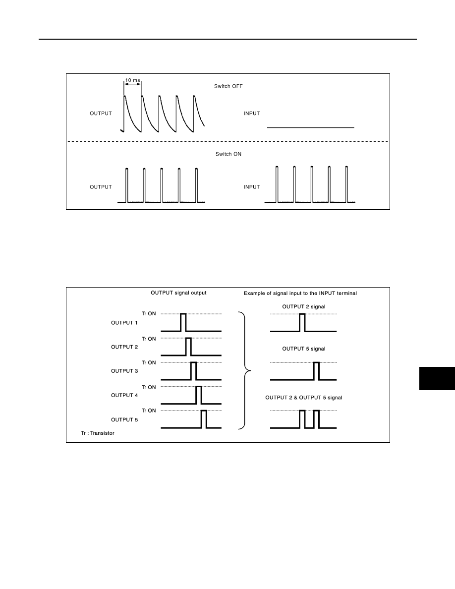
COMBINATION SWITCH READING FUNCTION
Description
• BCM reads the status of the combination switch at 10 ms intervals normally.
NOTE:
BCM reads the status of the combination switch at 60 ms intervals when BCM is controlled at low power
consumption control mode.
• BCM operates as follows and judges the status of the combination switch.
- It operates the transistor on OUTPUT side in the following order: OUTPUT 1
→ 2 → 3 → 4 → 5, and outputs
voltage waveform.
- The voltage waveform of OUTPUT corresponding to the formed circuit is input into the interface on INPUT
side if any (1 or more) switches are ON.
- It reads this change of the voltage as the status signal of the combination switch.
Operation Example
In the following operation example, the combination of the status signals of the combination switch is replaced
as follows: INPUT 1 - 5 to “1 - 5” and OUTPUT 1 - 5 to “A - E”.
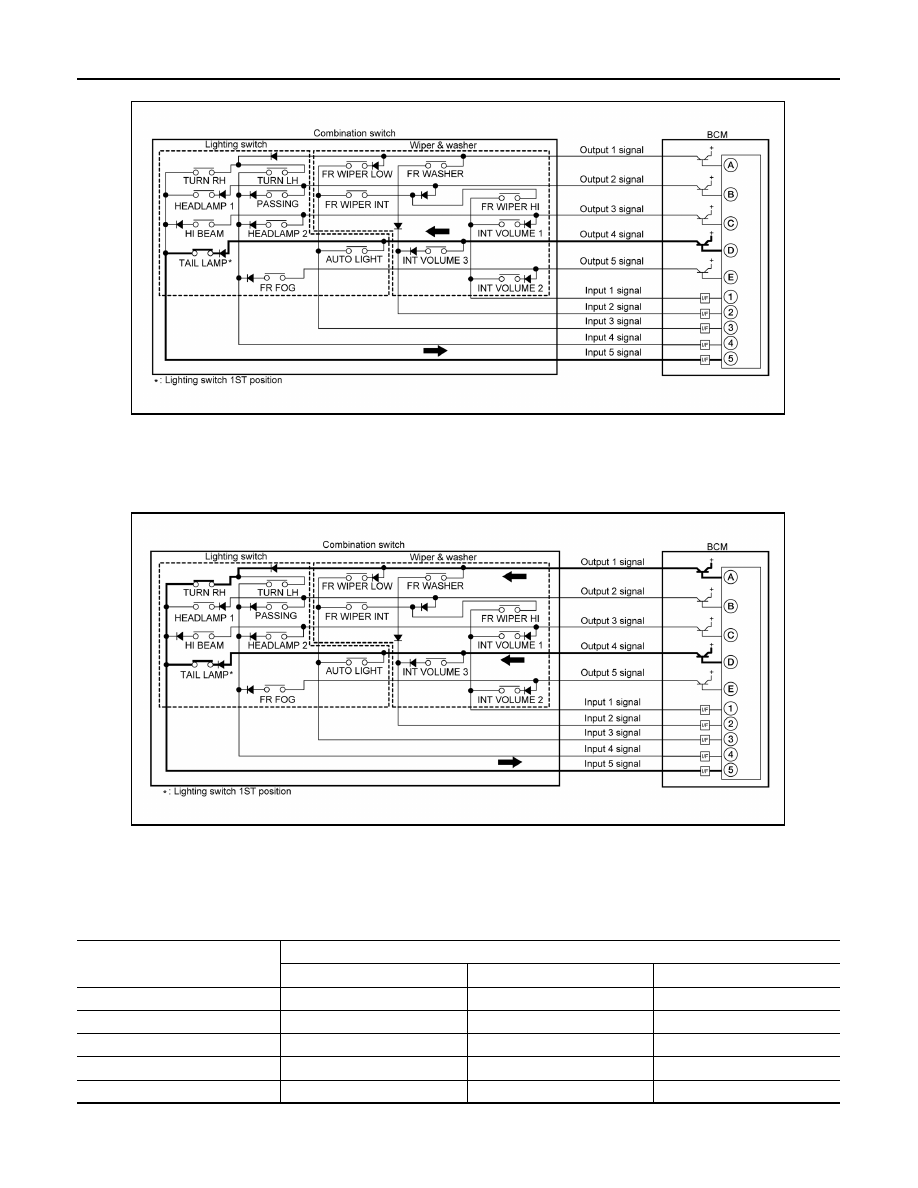
Example 1: When a switch (TAIL LAMP) is turned ON
JPMIA0609GB
JMMIA0326GB
EXL-14
< SYSTEM DESCRIPTION >
SYSTEM
• The circuit between OUTPUT 4 and INPUT 5 is formed when the TAIL LAMP switch is turned ON.
• BCM detects the combination switch status signal “5D” when the signal of OUTPUT 4 is input to INPUT 5.
• BCM judges that the TAIL LAMP switch is ON when the signal “5D” is detected.
Example 2: When some switches (TURN RH, TAIL LAMP) are turned ON
• The circuits between OUTPUT 1 and INPUT 5 and between OUTPUT 4 and INPUT 5 are formed when the
TURN RH switch and TAIL LAMP switch are turned ON.
• BCM detects the combination switch status signal “5AD” when the signals of OUTPUT 1 and OUTPUT 4 are
input to INPUT 5.
• BCM judges that the TURN RH switch and TAIL LAMP switch are ON when the signal “5AD” is detected.
WIPER INTERMITTENT DIAL POSITION
BCM judges the wiper intermittent dial 1 - 7 by the status of INT VOLUME 1, 2 and 3 switches.
AWMIA1361GB
AWMIA1362GB
Wiper intermittent
dial position
Switch status
INT VOLUME 1
INT VOLUME 2
INT VOLUME 3
1
ON
ON
ON
2
ON
ON
OFF
3
ON
OFF
OFF
4
OFF
OFF
OFF
5
OFF
OFF
ON
Нет комментариевНе стесняйтесь поделиться с нами вашим ценным мнением.
Текст