Nissan Sentra. Instruction — part 738
RSU-10
< REMOVAL AND INSTALLATION >
REAR SHOCK ABSORBER
Inspection
INFOID:0000000009758782
INSPECTION AFTER REMOVAL
Shock Absorber
Check the following items and replace the parts if necessary.
• Check the shock absorber for oil leaks, deformation, cracks, and other damage.
• Check the piston rod for damage, uneven wear, and distortion.
Bound Bumper, Bushing
Check for cracks and damage. Replace the parts if necessary.
Washer, Bound Bumper Cover, Distance Tube
• Check for cracks and damage. Replace the parts if necessary.
Disposal
INFOID:0000000009758783
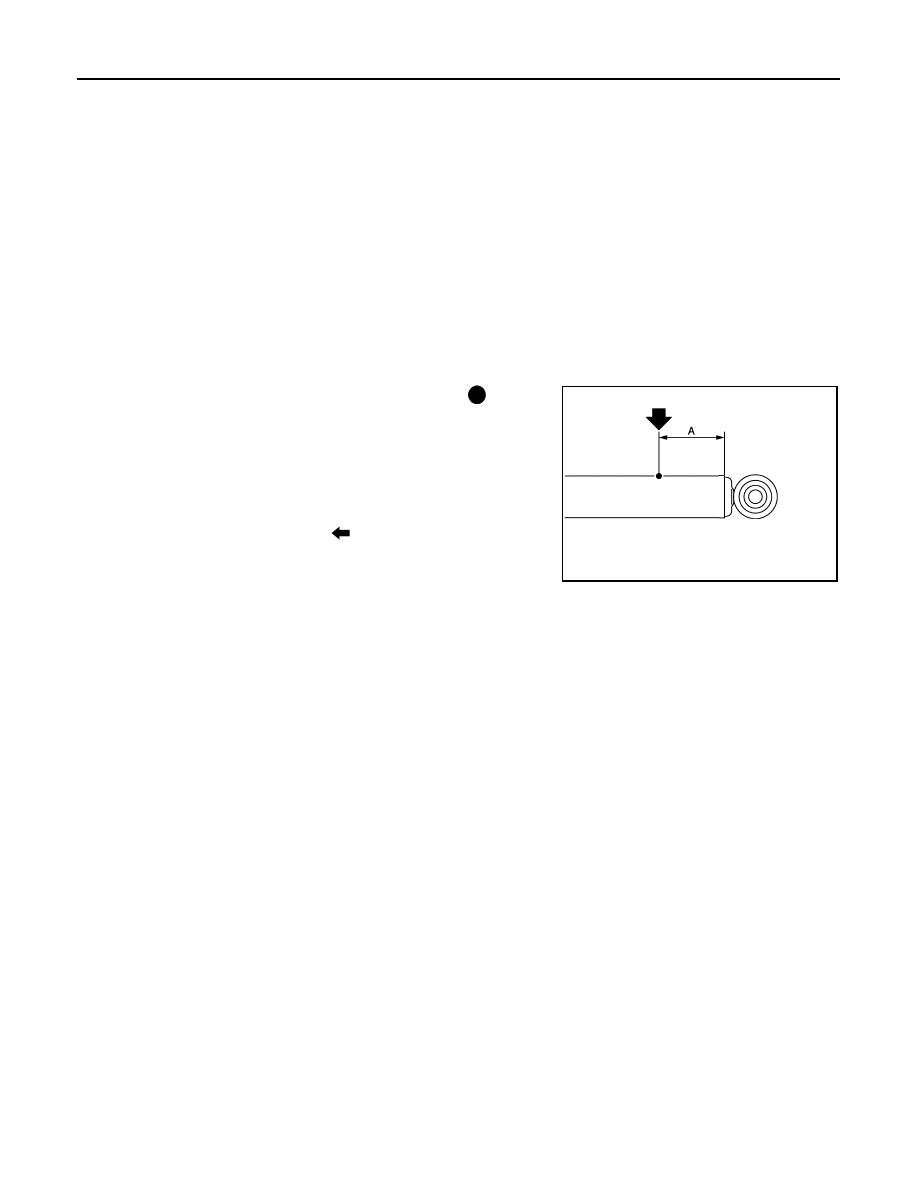
1. Set the shock absorber horizontally with the piston rod fully extended.
2. Drill a 2 – 3 mm (0.08 – 0.12 in) hole at the position ( ) from the
top as shown to release gas gradually.
CAUTION:
• Wear eye protection (safety glasses).
• Wear gloves.
• Be careful with metal chips or oil blown out by the com-
pressed gas.
NOTE:
• Drill vertically in this direction (
).
• Drill directly to the outer tube avoiding brackets.
• The gas is clear, colorless, odorless, and harmless.
3. Position the drilled hole downward and drain oil by moving the piston rod several times.
CAUTION:
Dispose of drained oil according to the law and local regulations.
(A)
: 20 – 30 mm (0.79 – 1.18 in)
JPEIA0161ZZ
COIL SPRING
RSU-11
< REMOVAL AND INSTALLATION >
C
D
F
G
H
I
J
K
L
M
A
B
RSU
N
O
P
COIL SPRING
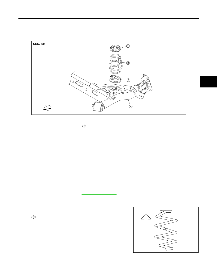
Exploded View
INFOID:0000000009758784
Removal and Installation
INFOID:0000000009758785
REMOVAL
1. Set a suitable jack under the rear suspension beam.
CAUTION:
• At this step, the jack must be set only for supporting the removal procedure. For details on jack-
ing up the vehicle, refer to
GI-31, "Garage Jack and Safety Stand and 2-Pole Lift"
• Do not damage the rear suspension beam with the jack.
2. Remove the lower shock absorber bolts. Refer to
3. Slowly lower the suitable jack. Remove the upper rubber seat, the coil spring, and the lower rubber seat
from the rear suspension beam.
CAUTION:
Make sure the rear suspension beam is stable when using the jack.
4. Inspect the components. Refer to
INSTALLATION
Installation is in the reverse order of removal.
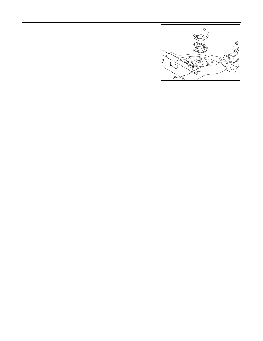
• Identify the upper side of the coil spring.
NOTE:
The top of the coil spring has a flat shape.
1.
Upper rubber seat
2.
Coil spring
3.
Lower rubber seat
4.
Rear suspension beam
Front
AWEIA0295ZZ
: Upper side
JSEIA0430ZZ
RSU-12
< REMOVAL AND INSTALLATION >
COIL SPRING
• Align the lower end of the coil spring with the steps on the lower
rubber seat.
Inspection
INFOID:0000000009758786
INSPECTION AFTER REMOVAL
Check the upper rubber seat, the lower rubber seat, and the coil spring for deformation, cracks, and damage.
Replace the parts if necessary.
JSEIA0431ZZ
REAR SUSPENSION BEAM
RSU-13
< REMOVAL AND INSTALLATION >
C
D
F
G
H
I
J
K
L
M
A
B
RSU
N
O
P
REAR SUSPENSION BEAM
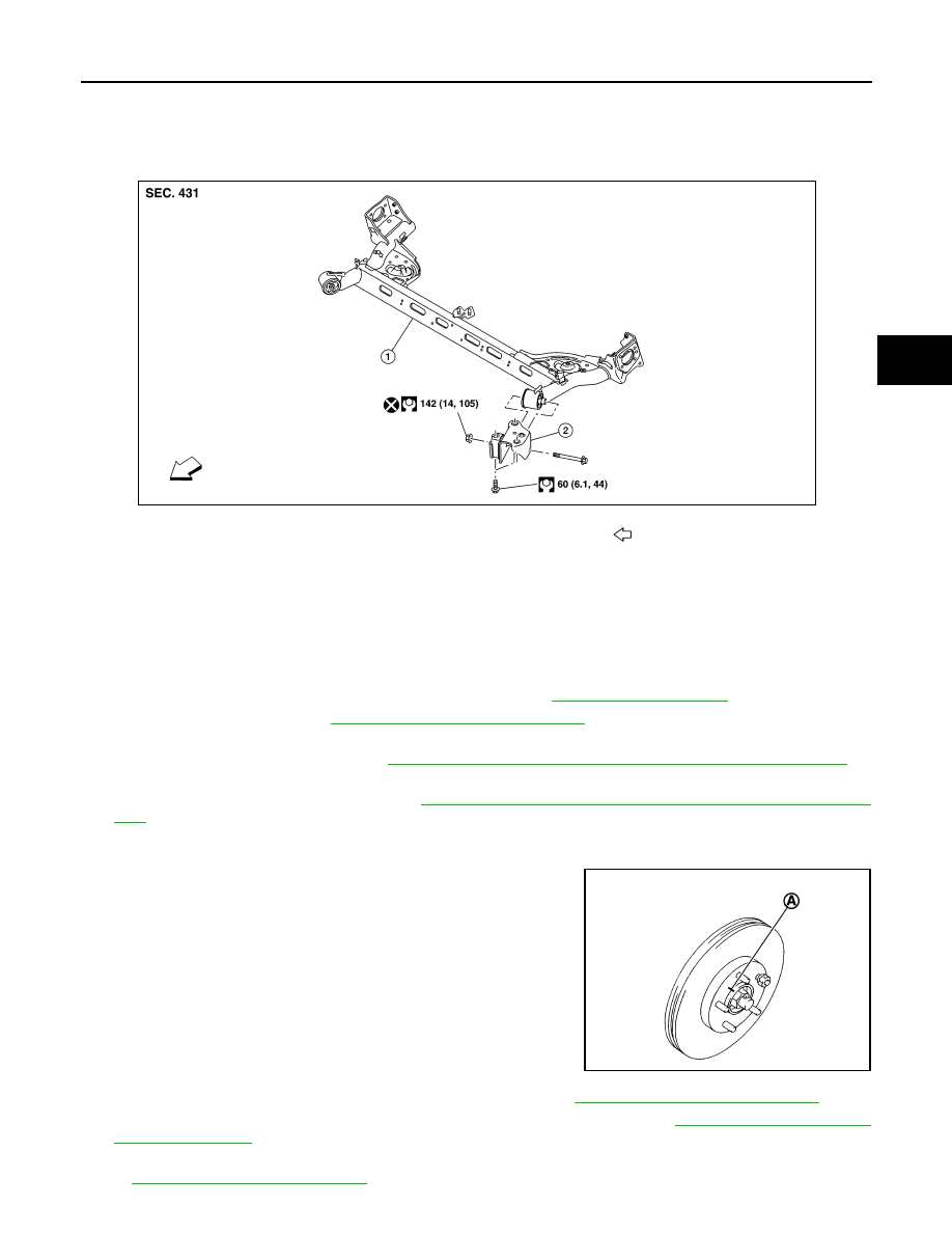
Exploded View
INFOID:0000000009758787
Removal and Installation
INFOID:0000000009758788
NOTE:
When removing components such as hoses, tubes, lines, etc., cap or plug openings to prevent fluid from spill-
ing.
REMOVAL
1. Remove the rear wheels and tires using power tool. Refer to
.
2. Drain the brake fluid. Refer to
CO-12, "Changing Engine Coolant"
.
3. Disconnect the wheel sensor harness from the retainers. Remove the wheel sensors and position the
wheel sensor harness aside. Refer to
BRC-107, "REAR WHEEL SENSOR : Removal and Installation"
.
4. Remove the brake caliper torque member bolts leaving the brake hoses attached. Position the brake cali-
pers aside with wire (if equipped). Refer to
BR-47, "BRAKE CALIPER ASSEMBLY : Removal and Installa-
CAUTION:
Do not depress the brake pedal when the brake caliper is removed.
5. Put alignment marks (A) on the disc brake rotors and on the
wheel hubs and bearings. Remove the disc brake rotors (if
equipped).
CAUTION:
Do not drop the disc brake rotor.
6. Remove the rear drum brake assemblies (if equipped). Refer to
BR-42, "Removal and Installation"
.
7. Remove the disc brake parking brake shoe assemblies (if equipped). Refer to
8. Disconnect the parking brake cables from the back plates, the rear suspension beam, and the body. Refer
PB-7, "Removal and Installation"
1.
Rear suspension beam
2.
Rear suspension arm bracket
Front
AWEIA0296ZZ
JPDIG0066ZZ
Нет комментариевНе стесняйтесь поделиться с нами вашим ценным мнением.
Текст