Nissan Sentra. Instruction — part 737
RSU-6
< PERIODIC MAINTENANCE >
WHEEL ALIGNMENT
WHEEL ALIGNMENT
Inspection
INFOID:0000000009758779
DESCRIPTION
Measure the wheel alignment under unladen conditions.
NOTE:
“Unladen conditions” means that fuel, engine coolant, and lubricants are full. Spare tire, jack, hand tools and
mats are in designated positions.
PRELIMINARY
Check the following:
1. Tires for improper air pressure and wear.
2. Road wheels for runout. Refer to
3. Wheel bearing axial end play. Refer to
.
4. Shock absorber operation.
5. Each mounting part of suspension for looseness and deformation.
6. Rear suspension beam for cracks, deformation, and other damage.
7. Vehicle height (posture).
GENERAL INFORMATION AND RECOMMENDATIONS
1. A Four-Wheel Thrust Alignment should be performed.
• This type of alignment is recommended for any NISSAN vehicle.
• The four-wheel “thrust” process helps ensure that the vehicle is properly aligned and the steering wheel
is centered.
• The alignment machine itself should be capable of accepting any NISSAN vehicle.
• The alignment machine should be checked to ensure that it is level.
2. Make sure the alignment machine is properly calibrated.
• Your alignment machine should be regularly calibrated in order to give correct information.
• Check with the manufacturer of your specific alignment machine for their recommended Service/Cali-
bration Schedule.
THE ALIGNMENT PROCESS
IMPORTANT: Use only the alignment specifications listed in this Instruction. Refer to
1. When displaying the alignment settings, many alignment machines use “indicators”: (Green/red, plus or
minus, Go/No Go). Do NOT use these indicators.
• The alignment specifications programmed into your alignment machine that operate these indicators
may not be correct.
• This may result in an ERROR.
2. Most camera-type alignment machines are equipped with both "Rolling Compensation" method and
optional "Jacking Compensation" method to "compensate" the alignment targets or head units.
"Rolling Compensation" is the preferred method.
• If using the "Rolling Compensation" method, after installing the alignment targets or head units, push or
pull on the rear wheel to move the vehicle. Do not push or pull the vehicle body.
• If using the "Jacking Compensation" method, after installing the alignment targets or head units, raise
the vehicle and rotate the wheels 1/2 turn both ways.
NOTE:
Do not use the "rolling compensation" if you are using sensor-type alignment equipment.
• Follow all instructions for the alignment machine you're using for more information.
CAMBER INSPECTION
• Measure camber of both right and left wheels with a suitable alignment gauge.
• If it is out of the specification value, inspect and replace any damaged or worn rear suspension parts.
Camber
: Refer to
.
WHEEL ALIGNMENT
RSU-7
< PERIODIC MAINTENANCE >
C
D
F
G
H
I
J
K
L
M
A
B
RSU
N
O
P
TOTAL TOE-IN INSPECTION
Measure the total toe-in using following procedure. If it is out of the specification, inspect and replace any
damaged or worn rear suspension parts.
WARNING:
• Always perform the following procedure on a flat surface.
• Make sure that no person is in front of the vehicle before pushing it.
1. Bounce the rear of the vehicle up and down to stabilize the vehicle height (posture).
2. Push the rear wheel to move the vehicle straight ahead about 5 m (16 ft).
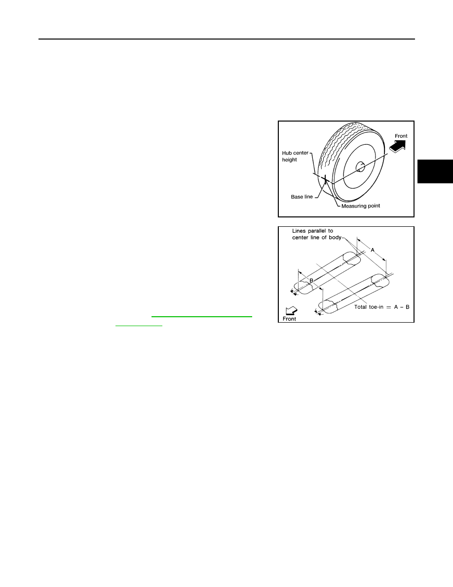
3. Put a mark on the base line of the tread (rear side) of both tires
at the same height of hub center. These are measuring points.
4. Measure the distance (A) from the rear side.
5. Push the rear wheel to move the vehicle slowly ahead and to
rotate the wheels 180 degrees (1/2 turn).
CAUTION:
If the wheels have rotated more than 180 degrees (1/2 turn),
try the above procedure again from the beginning. Do not
push the vehicle backward.
6. Measure the distance (B) from the front side.
SEIA0362E
Total toe-in
: Refer to
SFA234AC
RSU-8
< REMOVAL AND INSTALLATION >
REAR SHOCK ABSORBER
REMOVAL AND INSTALLATION
REAR SHOCK ABSORBER
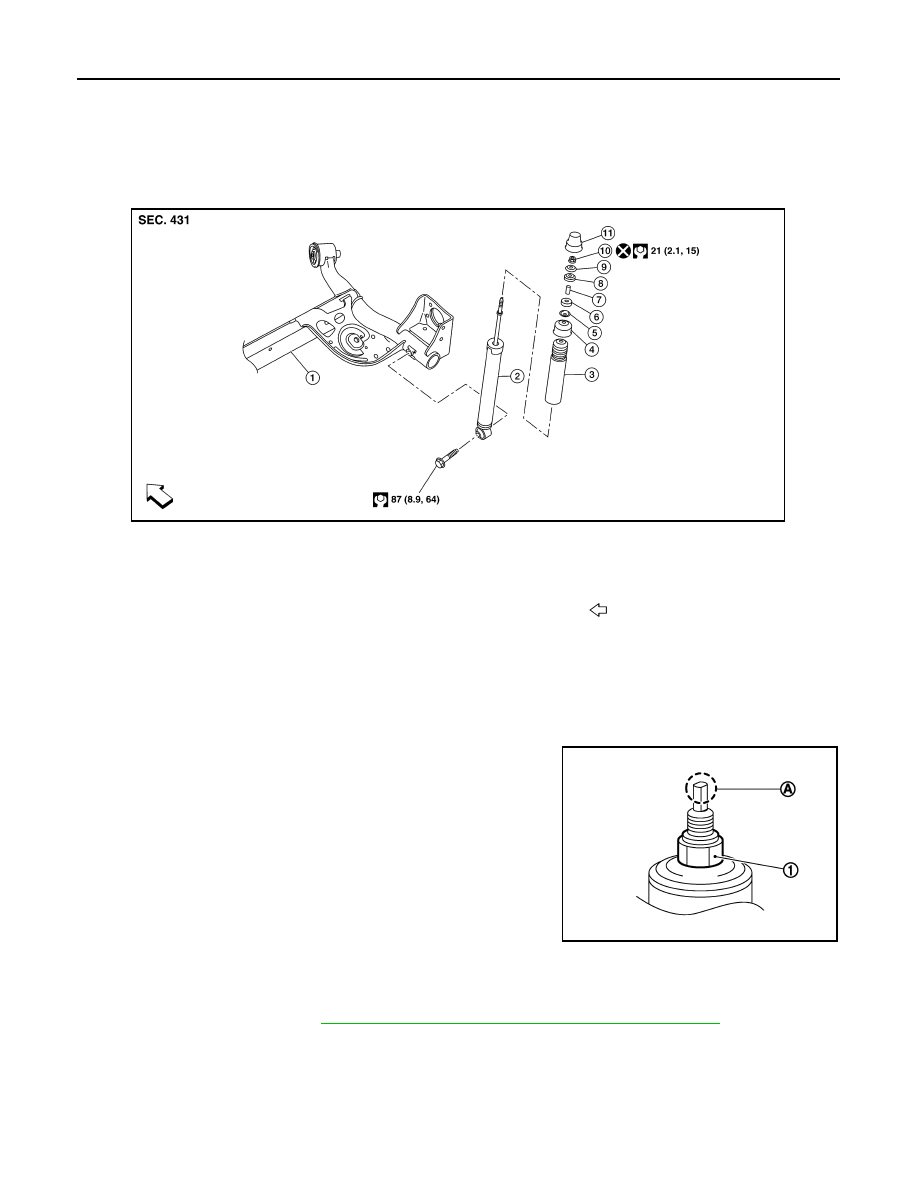
Exploded View
INFOID:0000000009758780
Removal and Installation
INFOID:0000000009758781
REMOVAL
1. Remove the rear shock tower access flap.
2. Remove the cap from the rear shock absorber.
3. Remove the piston rod lock nut (1).
NOTE:
To loosen the piston rod lock nut, hold the tip (A) of the piston
rod.
4. Remove the washer and the bushing.
5. Set a suitable jack under the rear suspension beam.
CAUTION:
• At this step, the jack must be set only for supporting the removal procedure. For details on jack-
ing up the vehicle, refer to
GI-31, "Garage Jack and Safety Stand and 2-Pole Lift"
.
• Do not damage the rear suspension beam with the jack.
• Make sure the rear suspension beam is stable when using the jack.
6. Remove the lower shock absorber bolt.
7. Remove the rear shock absorber.
8. Remove the bushing, the distance tube, the washer, the bound bumper cover, and the bound bumper
from the shock absorber.
1.
Rear suspension beam
2.
Shock absorber
3.
Bound bumper
4.
Bound bumper cover
5.
Washer
6.
Bushing
7.
Distance tube
8.
Bushing
9.
Washer
10. Piston rod lock nut
11. Cap
Front
AWEIA0294ZZ
JPEIB0241ZZ
REAR SHOCK ABSORBER
RSU-9
< REMOVAL AND INSTALLATION >
C
D
F
G
H
I
J
K
L
M
A
B
RSU
N
O
P
9. Inspect the components. Refer to
INSTALLATION
Installation is in the reverse order of removal.
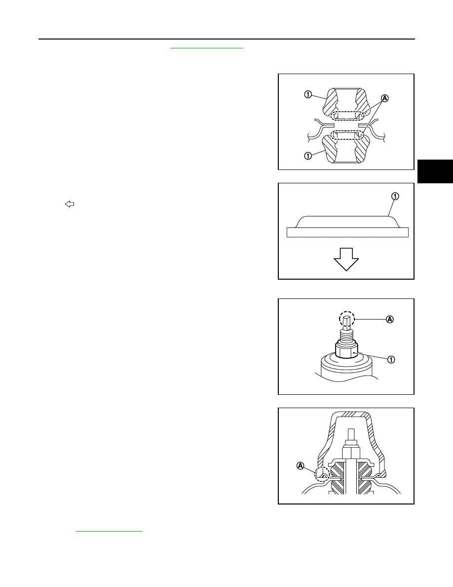
• To install the bushings (1), securely insert the protrusion (A) into
the hole in the vehicle body.
• Install the washer (1) in the direction shown.
• Perform the final tightening of the bolts and nuts under unladen conditions with the tires on level ground.
• Hold the tip (A) of the piston rod. Tighten the piston rod lock nut (1)
to the specification.
CAUTION:
Do not reuse the piston rod lock nut.
• When installing the cap, securely engage the cap groove (A) with
the flange on the vehicle body.
• After replacing the shock absorber, always follow the disposal procedure to discard the old shock absorber.
.
JPEIB0240ZZ
: Bushing side
JPEIB0248ZZ
JPEIB0241ZZ
JPEIB0244ZZ
Нет комментариевНе стесняйтесь поделиться с нами вашим ценным мнением.
Текст