Nissan Sentra. Instruction — part 681
PCS
DIAGNOSIS AND REPAIR WORK FLOW
PCS-77
< BASIC INSPECTION >
[POWER DISTRIBUTION SYSTEM]
C
D
E
F
G
H
I
J
K
L
B
A
O
P
N
BASIC INSPECTION
DIAGNOSIS AND REPAIR WORK FLOW
Work Flow
INFOID:0000000009755862
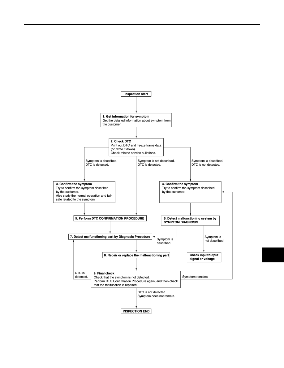
OVERALL SEQUENCE
DETAILED FLOW
JMKIA8652GB

PCS-78
< BASIC INSPECTION >
[POWER DISTRIBUTION SYSTEM]
DIAGNOSIS AND REPAIR WORK FLOW
1.
GET INFORMATION FOR SYMPTOM
1. Get detailed information from the customer about the symptom (the condition and the environment when
the incident/malfunction occurs).
2. Check operation condition of the component or system that is malfunctioning.
>> GO TO 2.
2.
CHECK DTC
1. Check DTC.
2. Perform the following procedure if DTC is detected.
-
Record DTC and freeze frame data (Print them out using CONSULT).
-
Erase DTC.
-
Study the relationship between the cause detected by DTC and the symptom described by the customer.
3. Check related service bulletins for information.
Are any symptoms described and any DTC detected?
Symptom is described, DTC is detected>>GO TO 3.
Symptom is described, DTC is not detected>>GO TO 4.
Symptom is not described, DTC is detected>>GO TO 5.
3.
CONFIRM THE SYMPTOM
Try to confirm the symptom described by the customer.
Also study the normal operation and fail-safe related to the symptom.
Verify relation between the symptom and the condition when the symptom is detected.
>> GO TO 5.
4.
CONFIRM THE SYMPTOM
Try to confirm the symptom described by the customer.
Verify relation between the symptom and the condition when the symptom is detected.
NOTE:
Freeze frame data is useful if the DTC is not detected.
>> GO TO 6.
5.
PERFORM DTC CONFIRMATION PROCEDURE
Perform DTC CONFIRMATION PROCEDURE for the detected DTC, and then check that DTC is detected
again. At this time, always connect CONSULT to the vehicle, and check self diagnostic results in real time.
If two or more DTCs are detected, refer to
BCS-48, "DTC Inspection Priority Chart"
, and determine trouble
diagnosis order.
Is DTC detected?
YES
>> GO TO 7.
NO
>> Refer to
GI-39, "Intermittent Incident"
.
6.
DETECT MALFUNCTIONING SYSTEM BY SYMPTOM DIAGNOSIS
Detect malfunctioning system according to SYMPTOM DIAGNOSIS based on the confirmed symptom in step
4, and determine the trouble diagnosis order based on possible causes and symptom.
Is the symptom described?
YES
>> GO TO 7.
NO
>> Monitor input data from related sensors or check voltage of related module terminals using CON-
SULT.
7.
DETECT MALFUNCTIONING PART BY DIAGNOSIS PROCEDURE
Inspect according to Diagnosis Procedure of the system.
Is malfunctioning part detected?
YES
>> GO TO 8.
NO
>> Refer to
GI-39, "Intermittent Incident"
.

PCS
DIAGNOSIS AND REPAIR WORK FLOW
PCS-79
< BASIC INSPECTION >
[POWER DISTRIBUTION SYSTEM]
C
D
E
F
G
H
I
J
K
L
B
A
O
P
N
8.
REPAIR OR REPLACE THE MALFUNCTIONING PART
1. Repair or replace the malfunctioning part.
2. Reconnect parts or connectors disconnected during Diagnosis Procedure again after repair and replace-
ment.
3. Check DTC. If DTC is detected, erase it.
>> GO TO 9.
9.
FINAL CHECK
When DTC is detected in step 2, perform DTC CONFIRMATION PROCEDURE again, and then check that the
malfunction is repaired securely.
When symptom is described by the customer, refer to confirmed symptom in step 3 or 4, and check that the
symptom is not detected.
Is DTC detected and does symptom remain?
YES-1 >> DTC is detected: GO TO 7.
YES-2 >> Symptom remains: GO TO 4.
NO
>> Inspection End.

PCS-80
< DTC/CIRCUIT DIAGNOSIS >
[POWER DISTRIBUTION SYSTEM]
U1000 CAN COMM CIRCUIT
DTC/CIRCUIT DIAGNOSIS
U1000 CAN COMM CIRCUIT
Description
INFOID:0000000009755863
LAN-7, "CAN COMMUNICATION SYSTEM : System Description"
.
DTC Logic
INFOID:0000000009755864
DTC DETECTION LOGIC
NOTE:
U1000 can be set if a module harness was disconnected and reconnected, perhaps during a repair. Confirm
that there are actual CAN diagnostic symptoms and a present DTC by performing the Self Diagnostic Result
procedure.
Diagnosis Procedure
INFOID:0000000009755865
1.
PERFORM SELF DIAGNOSTIC RESULT
1. Turn ignition switch ON and wait for 2 second or more.
2. Check “SELF- DIAG RESULTS”.
Is “CAN COMM CIRCUIT” displayed?
YES
>> Perform CAN Diagnosis as described in DIAGNOSIS section of CONSULT operation instruction.
NO
>> Refer to
GI-39, "Intermittent Incident"
.
CONSULT Display
DTC Detection Condition
Possible Cause
CAN COMM CIRCUIT
[U1000]
When any listed module cannot communicate
with CAN communication signal continuously for
2 seconds or more with ignition switch ON
In CAN communication system, any item (or
items) of the following listed below is malfunc-
tioning.
• Transmission
• Receiving (ECM)
• Receiving (VDC/TCS/ABS)
• Receiving (METER/M&A)
• Receiving (TCM)
• Receiving (IPDM E/R)
Нет комментариевНе стесняйтесь поделиться с нами вашим ценным мнением.
Текст