Nissan Sentra. Instruction — part 682

PCS
U1010 CONTROL UNIT (CAN)
PCS-81
< DTC/CIRCUIT DIAGNOSIS >
[POWER DISTRIBUTION SYSTEM]
C
D
E
F
G
H
I
J
K
L
B
A
O
P
N
U1010 CONTROL UNIT (CAN)
DTC Logic
INFOID:0000000009755866
DTC DETECTION LOGIC
Diagnosis Procedure
INFOID:0000000009755867
1.
REPLACE BCM
When DTC “U1010” is detected, replace BCM.
>> Replace BCM. Refer to
BCS-73, "Removal and Installation"
CONSULT Display
DTC Detection Condition
Possible Cause
CONTROL UNIT (CAN)
[U1010]
BCM detected internal CAN communication cir-
cuit malfunction.
BCM

PCS-82
< DTC/CIRCUIT DIAGNOSIS >
[POWER DISTRIBUTION SYSTEM]
B2614 ACC RELAY CIRCUIT
B2614 ACC RELAY CIRCUIT
DTC Logic
INFOID:0000000009755868
DTC DETECTION LOGIC
DTC CONFIRMATION PROCEDURE
1.
PERFORM DTC CONFIRMATION PROCEDURE
1. Turn ignition switch to ACC, and wait for 1 second or more.
2. Check “Self-diagnosis result” of BCM with CONSULT.
Is DTC detected?
YES
>> Go to
NO
>> Inspection End.
Diagnosis Procedure
INFOID:0000000009755869
Regarding Wiring Diagram information, refer to
.
1.
CHECK ACCESSORY RELAY-2 CONTROL SIGNAL
Check voltage between BCM connector M83 and ground.
Is the inspection result normal?
YES
>> Replace BCM. Refer to
BCS-73, "Removal and Installation"
NO
>> GO TO 2.
2.
CHECK ACCESSORY RELAY-2 CONTROL SIGNAL CIRCUIT
1. Turn ignition switch OFF.
2. Disconnect BCM connector M83 and accessory relay-2.
3. Check continuity between BCM connector M83 and accessory relay-2 connector M65.
4. Check continuity between BCM connector M83 and ground.
Is the inspection result normal?
YES
>> GO TO 3.
NO
>> Repair or replace harness.
CONSULT Display
DTC detecting condition
Possible cause
ACC RELAY CIRCUIT
[B2614]
An immediate operation of accessory relay is request-
ed by BCM, but there is no response for more than 1
second.
• Harness or connectors
• Accessory relay-2
• BCM
(+)
(–)
Condition
Voltage (V)
(Approx.)
BCM
Connector
Terminal
M83
75
Ground
Ignition switch
OFF
0
ACC or ON
Battery voltage
BCM
Accessory relay-2
Continuity
Connector
Terminal
Connector
Terminal
M83
75
M65
2
Yes
BCM
Ground
Continuity
Connector
Terminal
M83
75
No
PCS
B2614 ACC RELAY CIRCUIT
PCS-83
< DTC/CIRCUIT DIAGNOSIS >
[POWER DISTRIBUTION SYSTEM]
C
D
E
F
G
H
I
J
K
L
B
A
O
P
N
3.
CHECK ACCESSORY RELAY-2
PCS-83, "Component Inspection"
.
Is the inspection result normal?
YES
>> Replace BCM. Refer to
BCS-73, "Removal and Installation"
NO
>> Replace accessory relay-2.
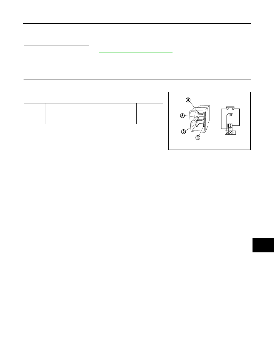
Component Inspection
INFOID:0000000009755870
1.
CHECK ACCESSORY RELAY-2
1. Turn ignition switch OFF.
2. Remove accessory relay-2.
3. Check the continuity between accessory relay-2 terminals.
Is the inspection result normal?
YES
>> Inspection End.
NO
>> Replace accessory relay-2.
Terminals
Condition
Continuity
3 and 5
12 V direct current supply between terminals 1 and 2
Yes
No current supply
No
PBIB0098E

PCS-84
< DTC/CIRCUIT DIAGNOSIS >
[POWER DISTRIBUTION SYSTEM]
B2615 BLOWER RELAY CIRCUIT
B2615 BLOWER RELAY CIRCUIT
DTC Logic
INFOID:0000000009755871
DTC DETECTION LOGIC
DTC CONFIRMATION PROCEDURE
1.
PERFORM DTC CONFIRMATION PROCEDURE
1. Turn ignition switch ON, and wait for 1 second or more.
2. Check “Self-diagnosis result” with CONSULT.
Is DTC detected?
YES
>> Go to
NO
>> Inspection End.
Diagnosis Procedure
INFOID:0000000009755872
Regarding Wiring Diagram information, refer to
.
1.
CHECK BLOWER RELAY POWER SUPPLY CIRCUIT
1. Turn ignition switch OFF.
2. Disconnect blower relay.
3. Disconnect BCM connector M83.
4. Check continuity between blower relay connector J-1 and BCM connector M83.
5. Check continuity between blower relay connector J-1 and ground.
Is the inspection result normal?
YES
>> GO TO 2.
NO
>> Repair or replace harness or connectors.
2.
CHECK BLOWER RELAY GROUND CIRCUIT
1. Check continuity between blower relay connector J-1 and ground.
Is the inspection result normal?
YES
>> GO TO 3.
NO
>> Repair or replace harness or connectors.
CONSULT Display
DTC Detection Condition
Possible Cause
BLOWER RELAY CIRCUIT
[B2615]
An immediate operation of front blower motor relay
is requested by BCM, but there is no response for
more than 1 second.
• Harness or connectors.
• Front blower motor relay.
• Fuse block J/B.
• BCM.
Blower relay
BCM
Continuity
Connector
Terminal
Connector
Terminal
J-1
2
M83
65
Yes
Blower relay
Ground
Continuity
Connector
Terminal
J-1
2
—
No
Blower relay
Ground
Continuity
Connector
Terminal
J-1
1
—
Yes
Нет комментариевНе стесняйтесь поделиться с нами вашим ценным мнением.
Текст