Nissan Sentra. Instruction — part 709
POWER SUPPLY AND GROUND CIRCUIT
PWC-33
< DTC/CIRCUIT DIAGNOSIS >
C
D
E
F
G
H
I
J
L
M
A
B
PWC
N
O
P
POWER WINDOW MAIN SWITCH : Diagnosis Procedure
INFOID:0000000009757236
Regarding Wiring Diagram information, refer to
.
Main Power Window And Door Lock/unlock Switch Power Supply Circuit Check
1.
CHECK POWER SUPPLY CIRCUIT
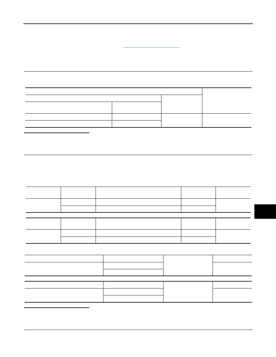
1. Turn ignition switch ON.
2. Check voltage between main power window and door lock/unlock switch connectors D5, D11 and ground.
Is the inspection result normal?
YES
>> GO TO 3.
NO
>> GO TO 2.
2.
CHECK HARNESS CONTINUITY
1. Turn ignition switch OFF.
2. Disconnect BCM, main power window and door lock/unlock switch, power window and door lock/unlock
switch RH, rear power window switch LH and rear power window switch RH.
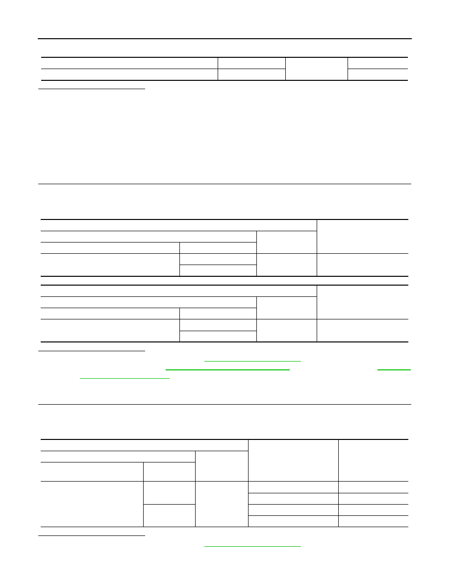
3. Check continuity between BCM connector and main power window and door lock/unlock switch connec-
tors.
With Intelligent Key system
Without Intelligent Key system
4. Check continuity between BCM connector M85 or M20 and ground.
With Intelligent Key system
Without Intelligent Key system
Is the inspection result normal?
YES
>> GO TO 4.
NO
>> Repair or replace the harness or connectors.
3.
CHECK GROUND CIRCUIT
1. Turn ignition switch OFF.
2. Disconnect main power window and door lock/unlock switch.
Terminal
Voltage
(Approx.)
(+)
(–)
Main power window and door lock/unlock switch
Terminal
D5
10
Ground
Battery voltage
D11
18
BCM
connector
Terminal
Main power window and door lock/unlock switch
connector
Terminal
Continuity
M85
92
D5
10
Yes
91
D11
18
BCM
connector
Terminal
Main power window and door lock/unlock switch
connector
Terminal
Continuity
M20
68
D5
10
Yes
69
D11
18
BCM connector
Terminal
Ground
Continuity
M85
91
No
92
BCM connector
Terminal
Ground
Continuity
M20
68
No
69
PWC-34
< DTC/CIRCUIT DIAGNOSIS >
POWER SUPPLY AND GROUND CIRCUIT
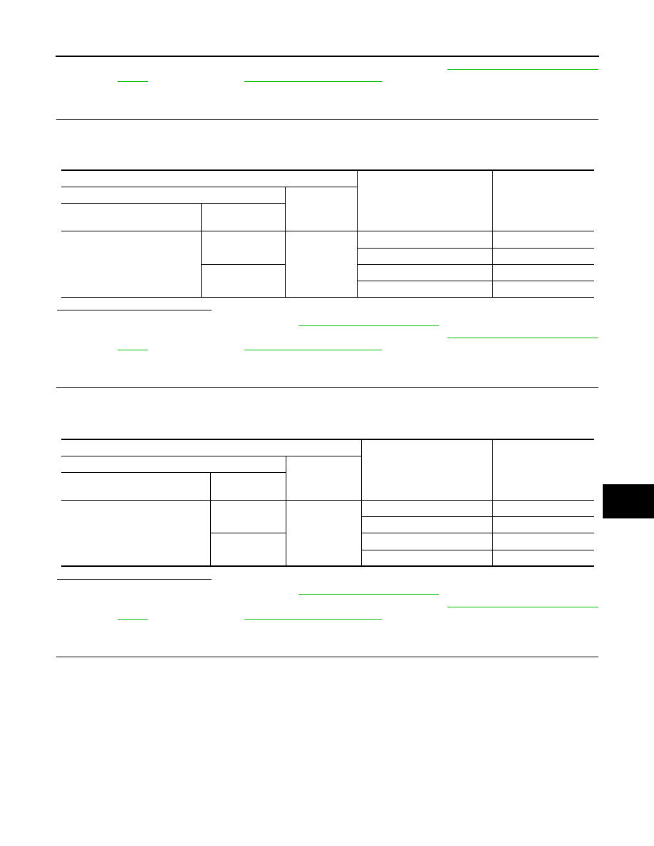
3. Check continuity between main power window and door lock/unlock switch connector D11 and ground.
Is the inspection result normal?
YES
>> Check main power window and door lock/unlock switch output signal (rear power window switch
LH) GO TO 5.
YES
>> Check main power window and door lock/unlock switch output signal (rear power window switch
RH) GO TO 6.
YES
>> Check main power window and door lock/unlock switch output signal (front power window switch
LH) GO TO 7.
YES
>> Check main power window and door lock/unlock switch output signal (front power window switch
RH) GO TO 8.
NO
>> Repair or replace the harness or connectors.
4.
CHECK BCM OUTPUT SIGNAL
1. Connect BCM.
2. Turn ignition switch ON.
3. Check voltage between BCM connector M85 or M20 and ground.
With Intelligent Key system
Without Intelligent Key system
Is the inspection result normal?
YES
>> Check intermittent incident. Refer to
GI-39, "Intermittent Incident"
.
NO
>> Replace BCM. Refer to
BCS-73, "Removal and Installation"
(without Intelligent Key).
5.
CHECK MAIN POWER WINDOW AND DOOR LOCK/UNLOCK SWITCH OUTPUT SIGNAL (REAR POW-
ER WINDOW SWITCH LH)
1. Connect main power window and door lock/unlock switch.
2. Turn ignition switch ON.
3. Check voltage between main power window and door lock/unlock switch D5 and ground.
Is the inspection result normal?
YES
>> Check intermittent incident. Refer to
GI-39, "Intermittent Incident"
.
Main power window and door lock/unlock switch connector
Terminal
Ground
Continuity
D11
1
Yes
Terminals
Voltage
(Approx.)
(+)
(–)
BCM connector
Terminal
M85
91
Ground
Battery voltage
92
Terminals
Voltage
(Approx.)
(+)
(–)
BCM connector
Terminal
M20
68
Ground
Battery voltage
69
Terminal
Window switch
position (rear LH)
Voltage
(Approx.)
(+)
(–)
Main power window and door lock/
unlock switch connector
Terminal
D5
9
Ground
UP
Battery voltage
DOWN
0
8
UP
0
DOWN
Battery voltage
POWER SUPPLY AND GROUND CIRCUIT
PWC-35
< DTC/CIRCUIT DIAGNOSIS >
C
D
E
F
G
H
I
J
L
M
A
B
PWC
N
O
P
NO
>> Replace main power window and door lock/unlock switch. Refer to
6.
CHECK MAIN POWER WINDOW AND DOOR LOCK/UNLOCK SWITCH OUTPUT SIGNAL (REAR POW-
ER WINDOW SWITCH RH)
1. Connect main power window and door lock/unlock switch.
2. Turn ignition switch ON.
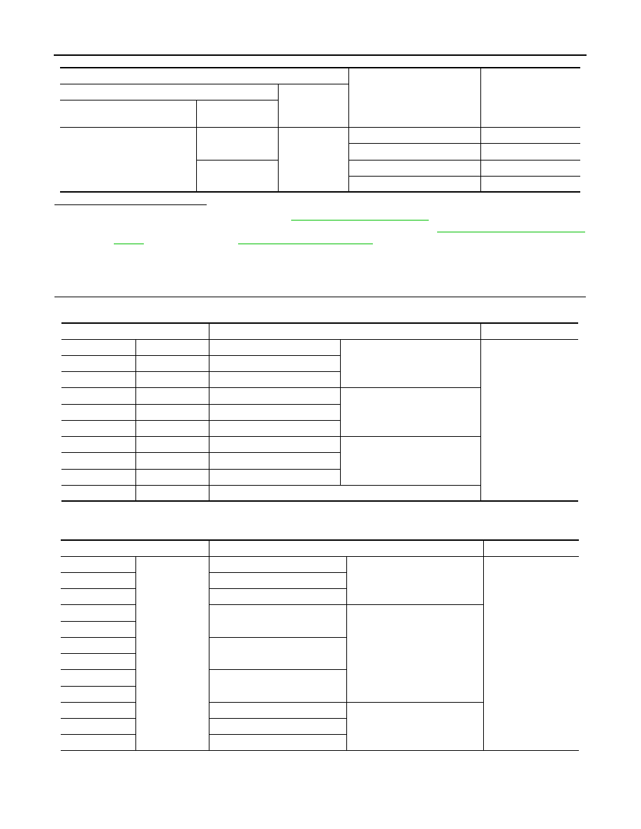
3. Check voltage between main power window and door lock/unlock switch D5 and ground.
Is the inspection result normal?
YES
>> Check intermittent incident. Refer to
GI-39, "Intermittent Incident"
.
NO
>> Replace main power window and door lock/unlock switch. Refer to
7.
CHECK MAIN POWER WINDOW AND DOOR LOCK/UNLOCK SWITCH OUTPUT SIGNAL (FRONT
POWER WINDOW SWITCH LH)
1. Connect main power window and door lock/unlock switch.
2. Turn ignition switch ON.
3. Check voltage between main power window and door lock/unlock switch D11 and ground.
Is the inspection result normal?
YES
>> Check intermittent incident. Refer to
GI-39, "Intermittent Incident"
.
NO
>> Replace main power window and door lock/unlock switch. Refer to
8.
CHECK MAIN POWER WINDOW AND DOOR LOCK/UNLOCK SWITCH OUTPUT SIGNAL (FRONT
POWER WINDOW SWITCH RH)
1. Connect main power window and door lock/unlock switch.
2. Turn ignition switch ON.
3. Check voltage between main power window and door lock/unlock switch D5 and ground.
Terminal
Window switch
position (rear RH)
Voltage
(Approx.)
(+)
(–)
Main power window and door
lock/unlock switch connector
Terminal
D5
7
Ground
UP
Battery voltage
DOWN
0
6
UP
0
DOWN
Battery voltage
Terminal
Window switch
position (front LH)
Voltage
(Approx.)
(+)
(–)
Main power window and door lock/
unlock switch connector
Terminal
D11
17
Ground
UP
Battery voltage
DOWN
0
19
UP
0
DOWN
Battery voltage
PWC-36
< DTC/CIRCUIT DIAGNOSIS >
POWER SUPPLY AND GROUND CIRCUIT
Is the inspection result normal?
YES
>> Check intermittent incident. Refer to
GI-39, "Intermittent Incident"
.
NO
>> Replace main power window and door lock/unlock switch. Refer to
. After that, refer to
POWER WINDOW MAIN SWITCH : Component Inspection
INFOID:0000000009757237
1.
CHECK MAIN POWER WINDOW AND DOOR LOCK/UNLOCK SWITCH
1. Check main power window and door lock/unlock switch D5.
2. Check continuity between main power window and door lock/unlock switch D5 (power window lock
switch) (Lock operation).
3. Check continuity between main power window and door lock/unlock switch D5 (power window lock
switch) (Unlock operation).
Terminal
Window switch
position (front RH)
Voltage
(Approx.)
(+)
(–)
Main power window and door
lock/unlock switch connector
Terminal
D5
16
Ground
UP
Battery voltage
DOWN
0
2
UP
0
DOWN
Battery voltage
Terminal
Main power window and door lock/unlock switch condition
Continuity
10
9
Rear LH
UP
Yes
10
7
Rear RH
10
16
Front RH
8
9
Rear LH
NEUTRAL
6
7
Rear RH
2
16
Front RH
10
8
Rear LH
DOWN
10
6
Rear RH
10
2
Front RH
1
12
-
Terminal
Main power window and door lock/unlock switch condition
Continuity
9
1
Rear LH
UP
No
7
Rear RH
16
Front RH
8
Rear LH
NEUTRAL
9
7
Rear RH
6
2
Front RH
16
8
Rear LH
DOWN
6
Rear RH
2
Front RH
Нет комментариевНе стесняйтесь поделиться с нами вашим ценным мнением.
Текст