Nissan Sentra. Instruction — part 710
POWER SUPPLY AND GROUND CIRCUIT
PWC-37
< DTC/CIRCUIT DIAGNOSIS >
C
D
E
F
G
H
I
J
L
M
A
B
PWC
N
O
P
Is the inspection result normal?
YES
>> Main power window and door lock/unlock switch is OK.
NO
>> Replace main power window and door lock/unlock switch. Refer to
POWER WINDOW MAIN SWITCH : Special Repair Requirement
INFOID:0000000009757238
1.
PERFORM INITIALIZATION PROCEDURE
Perform initialization procedure.
Is the inspection result normal?
YES
>> GO TO 2.
NO
>> Check intermittent incident. Refer to
GI-39, "Intermittent Incident"
.
2.
CHECK ANTI-PINCH OPERATION
Check anti-pinch operation.
Is the inspection result normal?
YES
>> Inspection End.
NO
>> Refer to
PWC-32, "POWER WINDOW MAIN SWITCH : Component Function Check"
FRONT POWER WINDOW SWITCH
FRONT POWER WINDOW SWITCH : Description
INFOID:0000000009757239
• BCM supplies power.
• Front power window motor RH will be operated if power window and door lock/unlock switch RH is operated.
FRONT POWER WINDOW SWITCH : Component Function Check
INFOID:0000000009757240
Power Window And Door Lock/unlock Switch RH
1.
CHECK POWER WINDOW MOTOR FUNCTION
Check front power window motor operation with power window and door lock/unlock switch RH.
Is the inspection result normal?
YES
>> Power window and door lock/unlock switch RH power supply and ground circuit are OK.
NO
>> Refer to
PWC-37, "FRONT POWER WINDOW SWITCH : Diagnosis Procedure"
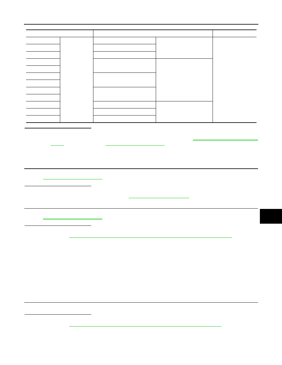
FRONT POWER WINDOW SWITCH : Diagnosis Procedure
INFOID:0000000009757241
Terminal
Main power window and door lock/unlock switch condition
Continuity
9
1
Rear LH
UP
Yes
7
Rear RH
16
Front RH
8
Rear LH
NEUTRAL
9
7
Rear RH
6
2
Front RH
16
8
Rear LH
DOWN
6
Rear RH
2
Front RH
PWC-38
< DTC/CIRCUIT DIAGNOSIS >
POWER SUPPLY AND GROUND CIRCUIT
Regarding Wiring Diagram information, refer to
.
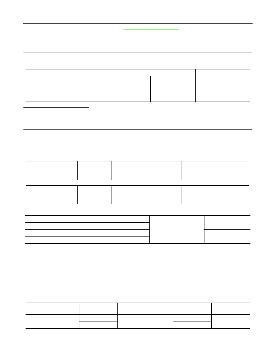
Power Window And Door Lock/Unlock Switch RH Power Supply Circuit Check
1.
CHECK POWER SUPPLY CIRCUIT (POWER WINDOW AND DOOR LOCK/UNLOCK SWITCH RH)
1. Turn ignition switch ON.
2. Check voltage between power window and door lock/unlock switch RH connector D104 and ground.
Is the inspection result normal?
YES
>> GO TO 3.
NO
>> GO TO 2.
2.
CHECK HARNESS CONTINUITY
1. Turn ignition switch OFF.
2. Disconnect BCM, power window and door lock/unlock switch RH, rear power window switch LH and rear
power window switch RH.
3. Check continuity between BCM connector M85 or M20 and power window and door lock/unlock switch
RH connector D104.
With Intelligent Key system
Without Intelligent Key system
4. Check continuity between BCM connector M85 or M20 and ground.
Is the inspection result normal?
YES
>> GO TO 4.
NO
>> Repair or replace the harness or connectors.
3.
CHECK HARNESS CONTINUITY (POWER WINDOW AND DOOR LOCK/UNLOCK SWITCH RH)
1. Turn ignition switch OFF.
2. Disconnect main power window and door lock/unlock switch and power window and door lock/unlock
switch RH.
3. Check continuity between main power window and door lock/unlock switch connector D5 and power win-
dow and door lock/unlock switch RH connector D104.
4. Check continuity between main power window and door lock/unlock switch connector D5 and ground.
Terminal
Voltage
(Approx.)
(+)
(–)
Power window and door lock/unlock
switch RH connector
Terminal
D104
8
Ground
Battery voltage
BCM connector
Terminal
Power window and door lock/unlock
switch RH connector
Terminal
Continuity
M85
92
D104
8
Yes
BCM connector
Terminal
Power window and door lock/unlock
switch RH connector
Terminal
Continuity
M20
68
D104
8
Yes
BCM
Ground
Continuity
Connector
Terminal
M85 (with Intelligent Key system)
92
No
M20 (without Intelligent Key system)
68
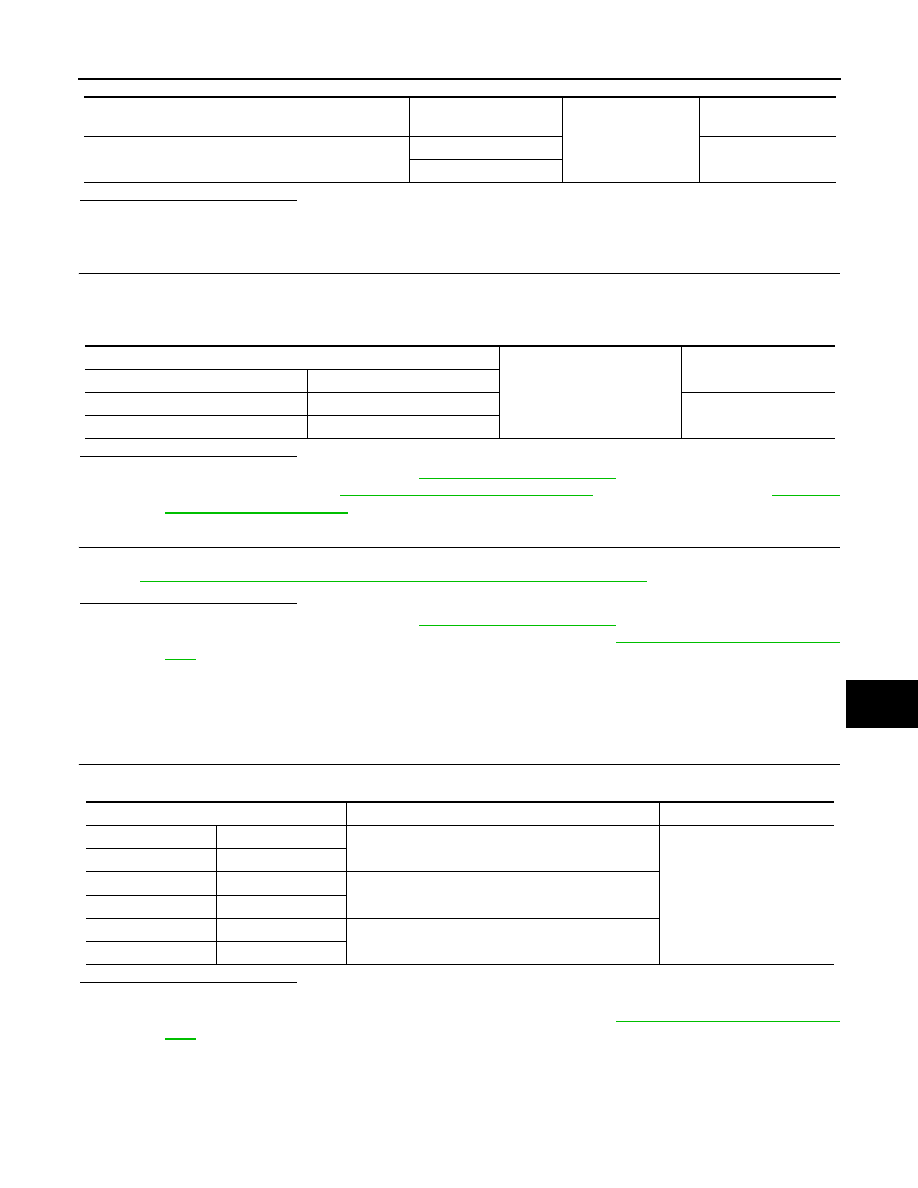
Main power window and door
lock/unlock switch connector
Terminal
Power window and door lock/
unlock switch RH connector
Terminal
Continuity
D5
2
D104
11
Yes
16
12
POWER SUPPLY AND GROUND CIRCUIT
PWC-39
< DTC/CIRCUIT DIAGNOSIS >
C
D
E
F
G
H
I
J
L
M
A
B
PWC
N
O
P
Is the inspection result normal?
YES
>> GO TO 5
NO
>> Repair or replace the harness or connectors.
4.
CHECK BCM OUTPUT SIGNAL
1. Connect BCM.
2. Turn ignition switch ON.
3. Check voltage between BCM connector M85 or M20 and ground.
Is the inspection result normal?
YES
>> Check intermittent incident. Refer to
GI-39, "Intermittent Incident"
.
NO
>> Replace BCM. Refer to
BCS-73, "Removal and Installation"
(with Intelligent Key) or
(without Intelligent Key).
5.
CHECK POWER WINDOW AND DOOR LOCK/UNLOCK SWITCH RH
Check power window and door lock/unlock switch RH.
PWC-39, "FRONT POWER WINDOW SWITCH : Component Inspection"
.
Is the inspection result normal?
YES
>> Check intermittent incident. Refer to
GI-39, "Intermittent Incident"
.
NO
>> Replace power window and door lock/unlock switch RH. Refer to
PWC-71, "Removal and Installa-
.
FRONT POWER WINDOW SWITCH : Component Inspection
INFOID:0000000009757242
COMPONENT INSPECTION
1.
CHECK POWER WINDOW AND DOOR LOCK/UNLOCK SWITCH RH
Check power window and door lock/unlock switch RH D104.
Is the inspection result normal?
YES
>> Power window and door lock/unlock switch RH is OK.
NO
>> Replace power window and door lock/unlock switch RH. Refer to
PWC-71, "Removal and Installa-
.
REAR POWER WINDOW SWITCH
REAR POWER WINDOW SWITCH : Description
INFOID:0000000009757243
• BCM supplies power.
Main power window and door lock/unlock switch con-
nector
Terminal
Ground
Continuity
D5
2
No
16
BCM
Ground
Continuity
Connector
Terminal
M85 (with Intelligent Key system)
92
No
M20 (without Intelligent Key system)
68
Terminal
Power window switch condition
Continuity
8
7
UP
Yes
11
6
12
7
NEUTRAL
6
11
8
6
DOWN
7
12
PWC-40
< DTC/CIRCUIT DIAGNOSIS >
POWER SUPPLY AND GROUND CIRCUIT
• Rear power window motor will be operated if rear power window switch is operated. Rear power window
switch.
REAR POWER WINDOW SWITCH : Component Function Check
INFOID:0000000009757244
Rear Power Window Switch
1.
CHECK REAR POWER WINDOW MOTOR FUNCTION
Check rear power window motor operation with rear power window switch.
Is the inspection result normal?
YES
>> Rear power window switch power supply and ground circuit are OK.
NO
>> Refer to
PWC-40, "REAR POWER WINDOW SWITCH : Diagnosis Procedure"
.
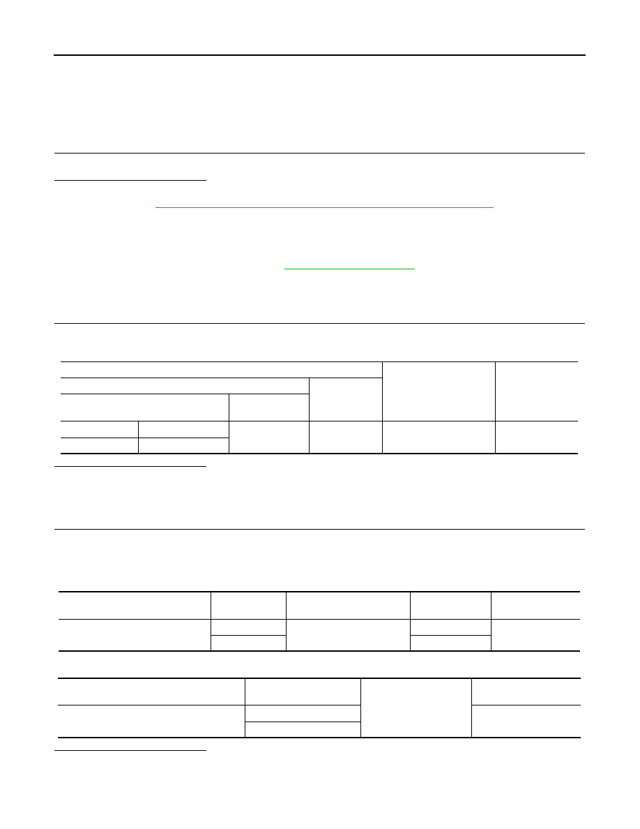
REAR POWER WINDOW SWITCH : Diagnosis Procedure
INFOID:0000000009757245
Regarding Wiring Diagram information, refer to
.
Rear Power Window Switch Power Supply Circuit Check
1.
CHECK POWER SUPPLY CIRCUIT
1. Turn ignition switch ON.
2. Check voltage between rear power window switch connector D203 or D303 and ground.
Is the inspection result normal?
YES
>> GO TO 2 (Rear power window switch LH).
YES
>> GO TO 3 (Rear power window switch RH).
NO
>> GO TO 4.
2.
CHECK HARNESS CONTINUITY (REAR POWER WINDOW SWITCH LH)
1. Turn ignition switch OFF.
2. Disconnect main power window and door lock/unlock switch and rear power window switch LH.
3. Check continuity between main power window and door lock/unlock switch connector D5 and rear power
window switch LH connector D203.
4. Check continuity between main power window and door lock/unlock switch connector D5 and ground.
Is the inspection result normal?
YES
>> GO TO 5.
NO
>> Repair or replace the harness or connectors.
Terminal
Condition
Voltage
(Approx.)
(+)
(–)
Rear power window
switch connector
Terminal
LH
D203
6
Ground
Ignition switch ON
Battery voltage
RH
D303
Main power window and door lock/
unlock switch connector
Terminal
Rear power window switch
LH connector
Terminal
Continuity
D5
8
D203
7
Yes
9
4
Main power window and door lock/unlock
switch connector
Terminal
Ground
Continuity
D5
8
No
9
Нет комментариевНе стесняйтесь поделиться с нами вашим ценным мнением.
Текст