Nissan Sentra. Instruction — part 862

TM-84
< SYSTEM DESCRIPTION >
[CVT: RE0F11A]
COMPONENT PARTS
3.
Shift lock release button
Forcibly releases the shift lock when pressed.
4.
Stop lamp switch
• The stop lamp switch turns ON when the brake pedal is depressed.
• When the stop lamp switch turns ON, the shift lock solenoid is energized.
No.
Component
Function
STRUCTURE AND OPERATION
TM-85
< SYSTEM DESCRIPTION >
[CVT: RE0F11A]
C
E
F
G
H
I
J
K
L
M
A
B
TM
N
O
P
STRUCTURE AND OPERATION
TRANSAXLE
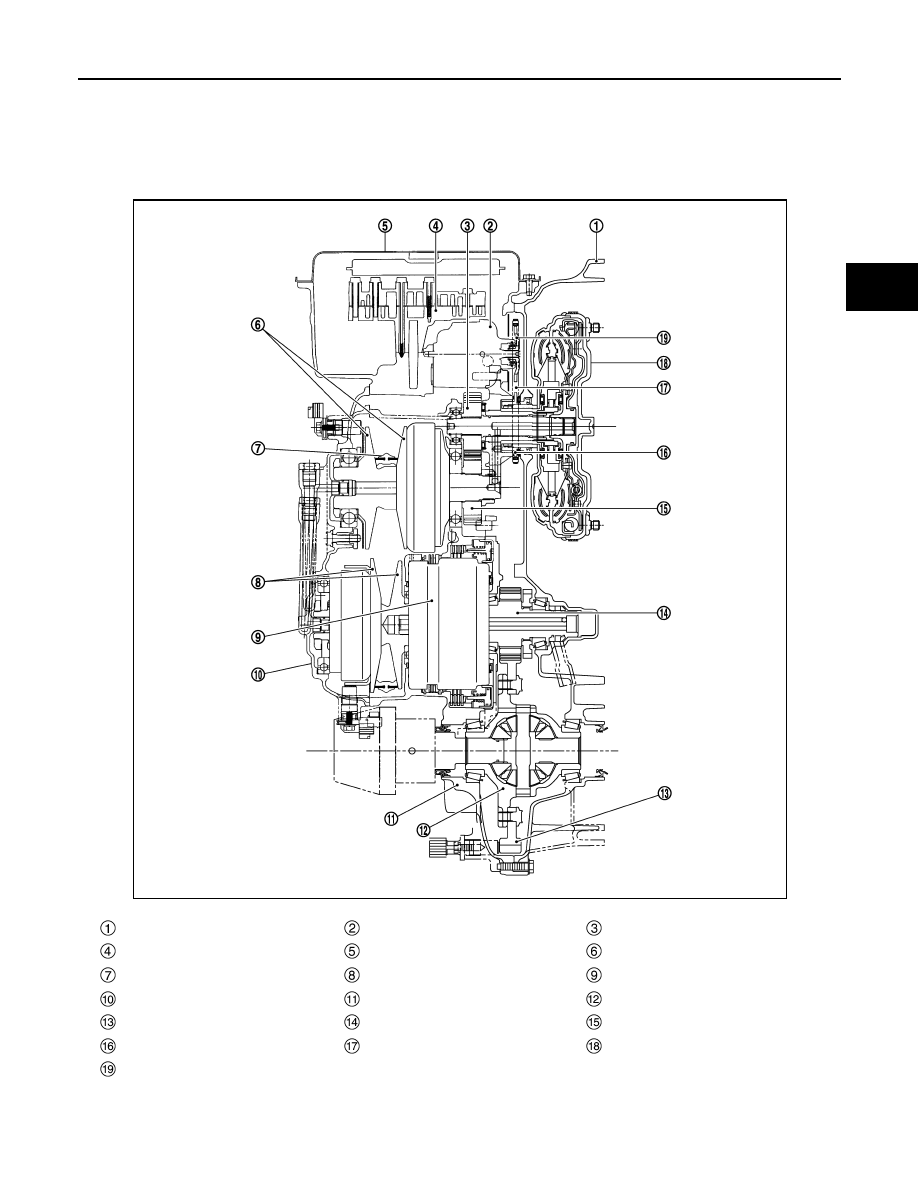
TRANSAXLE : Cross-Sectional View
INFOID:0000000009759337
Converter housing
Oil pump
Counter drive gear
Control valve
Oil pan
Primary pulley
Steel belt
Secondary pulley
Planetary gear (auxiliary gearbox)
Side cover
Transaxle case
Differential case
Final gear
Reduction gear
Counter driven gear
Drive sprocket
Oil pump chain
Torque converter
Driven sprocket
JSDIA1777ZZ
TM-86
< SYSTEM DESCRIPTION >
[CVT: RE0F11A]
STRUCTURE AND OPERATION
TRANSAXLE : Operation Status
INFOID:0000000009759338
×: Engaged or applied.
TRANSAXLE : Transaxle Mechanism
INFOID:0000000009759339
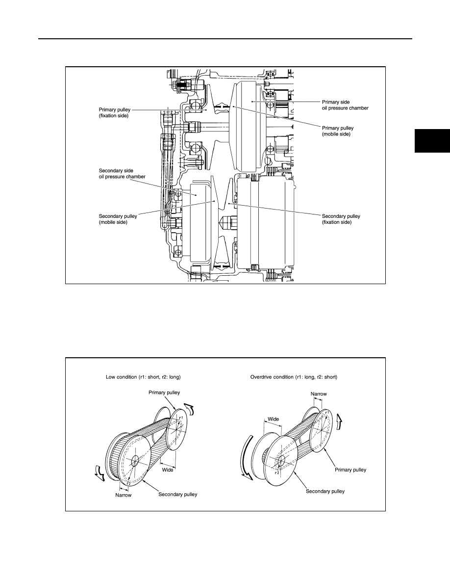
BELT & PULLEY
Mechanism
It is composed of a pair of pulleys (the groove width is changed freely in the axial direction) and the steel belt
(the steel plates are placed continuously and the belt is guided with the multilayer steel rings on both sides).
The groove width changes according to wrapping radius of steel belt and pulley from low status to overdrive
status continuously with non-step. It is controlled with the oil pressures of primary pulley and secondary pulley.
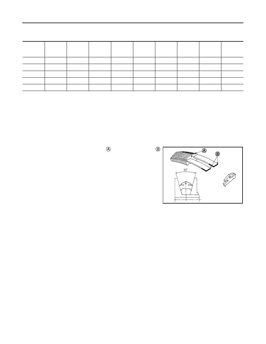
Steel belt
It is composed of multiple steel plates and two steel rings
stacked to a several number. The feature of this steel belt transmits
power with compression of the steel plate in contrast with transmis-
sion of power in pulling with a rubber belt. Friction force is required
with the pulley slope to transmit power from the steel plate. The force
is generated with the following mechanism:
Oil pressure applies to the secondary pulley to nip the plate.
⇒The
plate is pushed and extended outward.
⇒The steel ring shows with-
stands.
⇒Pulling force is generated on the steel ring. ⇒The plate of
the primary pulley is nipped between the pulley.
⇒Friction force is
generated between the steel belt and the pulley.
Therefore, responsibilities are divided by the steel plate that trans-
mits the power with compression and the steel ring that maintains necessary friction force. In this way, the
tension of the steel ring is distributed on the entire surface and stress variation is limited, resulting in good
durability.
Pulley
Selector le-
ver posi-
tion
Parking
mecha-
nism
Counter
gear set
Low brake High clutch
Reverse
brake
Primary
pulley
Secondary
pulley
Steel belt
Reduction
gear set
P
×
×
×
×
×
R
×
×
×
×
×
×
N
×
×
×
×
D
×
× (1GR)
× (2GR)
×
×
×
×
L
×
× (1GR)
× (2GR)
×
×
×
×
JSDIA1966ZZ
STRUCTURE AND OPERATION
TM-87
< SYSTEM DESCRIPTION >
[CVT: RE0F11A]
C
E
F
G
H
I
J
K
L
M
A
B
TM
N
O
P
The primary pulley (input shaft side) and the secondary pulley (output shaft side) have the shaft with slope
(fixed cone surface), movable sheave (movable cone surface that can move in the axial direction) and oil pres-
sure chamber at the back of the movable sheave.
Pulley gear shifting operation
• Pulley gear shifting operation
The movable sheave slides on the shaft to change the groove width of the pulley. Input signals of engine
load (accelerator pedal opening), engine revolution and gear ratio (vehicle speed) change the operation
pressures of the primary pulley and the secondary pulley, and controls the pulley groove width. Along with
change of the pulley groove width, the belt contact radius is changed. This allows continuous and stepless
gear shifting from low to overdrive. “The contact radius ratio of each pulley in contact with the belt x auxiliary
gearbox gear ratio” is the gear ratio.
AUXILIARY GEARBOX MECHANISM
1st, 2nd and reverse gears are changed with the planetary gear mechanism.
JSDIA1779GB
JSDIA1967GB
Нет комментариевНе стесняйтесь поделиться с нами вашим ценным мнением.
Текст