Nissan Sentra. Instruction — part 863
TM-88
< SYSTEM DESCRIPTION >
[CVT: RE0F11A]
STRUCTURE AND OPERATION
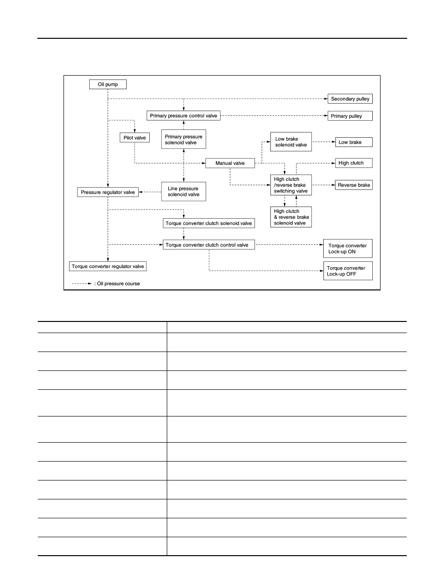
TRANSAXLE : Oil Pressure System
INFOID:0000000009759340
Oil pressure required for operation of the transaxle transmission mechanism is generated by oil pump, oil
pressure control valve, solenoid valve, etc.
TRANSAXLE : Component Description
INFOID:0000000009759341
JSDIA1826GB
Part name
Function
Torque converter
It is composed of the cover converter, turbine assembly, stator, pump impeller assem-
bly, etc. It increases the engine torque and transmits the power to the transaxle.
Oil pump
Through the oil pump drive chain, it uses the vane oil pump driven by the engine. It gen-
erates necessary oil pressure to circulate fluid and to operate the clutch and brake.
Counter gear set
The power from the torque converter is transmitted to the primary pulley through the
counter drive gear and the counter driven gear.
Belt & pulley (Continuously variable transmis-
sion)
It is composed of the primary pulley, secondary pulley, steel belt, etc. and the mecha-
nism performs shifting, changes the gear ratio and transmits the power with oil pressure
from the control valve.
Auxiliary gearbox (stepped transmission)
It is composed of the planetary gear, multi-disc clutch, multi-disc brake, etc. and the
mechanism performs shifting (1-2 gear shifting and reverse) with oil pressure from the
control valve.
Reduction gear set
Conveys power from the transmission mechanism to the reduction gear and the final
gear.
Parking mechanism
When the shift lever is changed to P position, the mechanism fixes the parking gear (in-
tegrated with the reduction gear) and the fixes the output shaft.
Control valve
Controls oil pressure from the oil pump to the pressure suitable for the line pressure
control system, shift control system, lock-up control system and lubrication system.
Pressure regulator valve
Adjusts the discharge pressure from the oil pump to the optimum pressure (line pres-
sure) corresponding to the driving condition.
Torque converter regulator valve
Adjusts the feed pressure to the torque converter to the optimum pressure correspond-
ing to the driving condition.
Pilot valve
Adjusts line pressure and produces a constant pressure (pilot pressure) necessary for
activating each solenoid valve.
STRUCTURE AND OPERATION
TM-89
< SYSTEM DESCRIPTION >
[CVT: RE0F11A]
C
E
F
G
H
I
J
K
L
M
A
B
TM
N
O
P
FLUID COOLER & FLUID WARMER SYSTEM
FLUID COOLER & FLUID WARMER SYSTEM : System Description
INFOID:0000000009759342
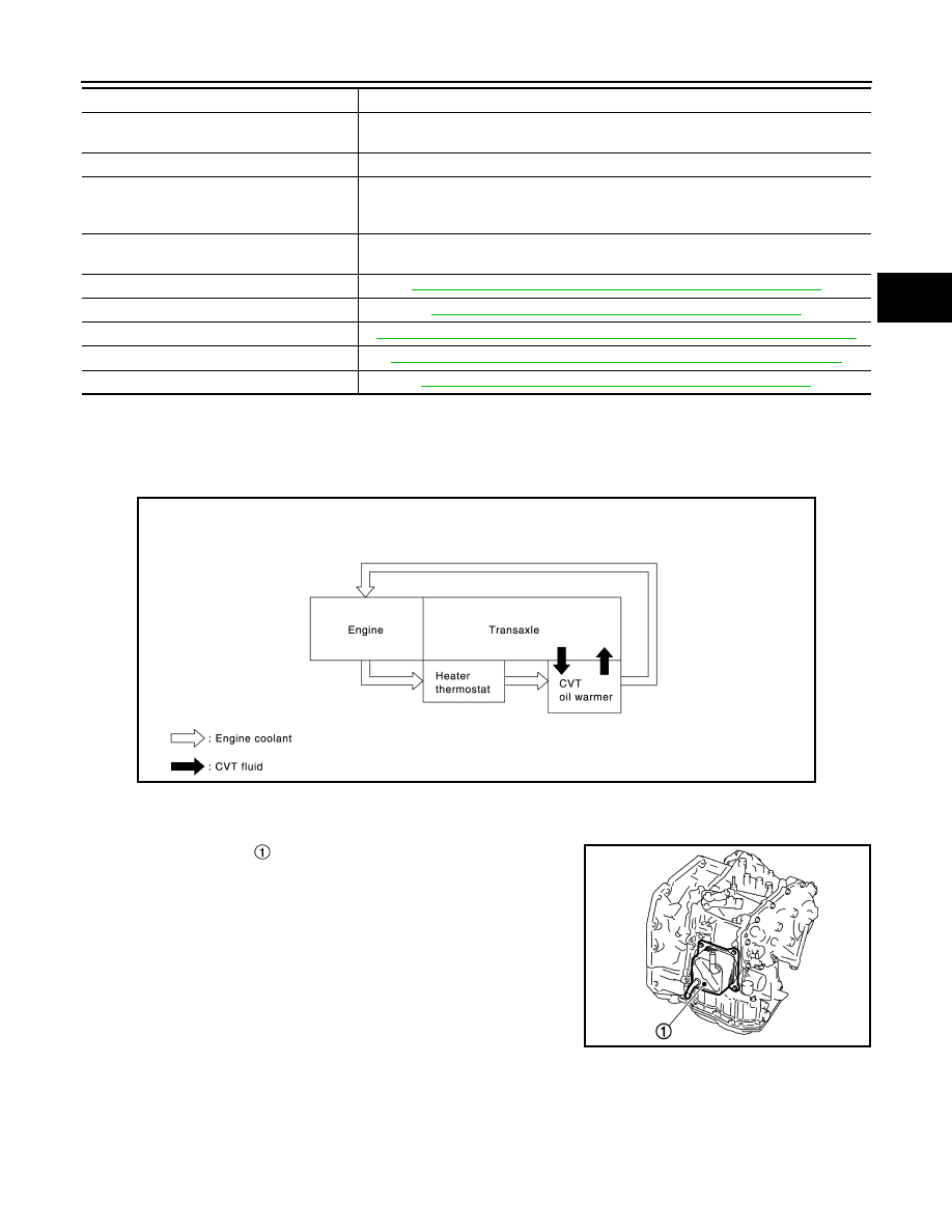
CVT FLUID COOLER SCHEMATIC
COMPONENT DESCRIPTION
CVT Oil Warmer
• The CVT oil warmer is installed on the front part of transaxle
assembly.
• When engine is started while engine and CVT are cold, engine
coolant temperature rises more quickly than CVT fluid tempera-
ture. CVT oil warmer is provided with two circuits for CVT and
engine coolant respectively so that warmed engine coolant warms
CVT quickly. This helps shorten CVT warming up time, improving
fuel economy.
• A cooling effect is obtained when CVT fluid temperature is high.
Heater Thermostat
Instruction valve
Distributes the clutch and brake operation pressures (pilot pressure) corresponding to
each shift position.
High clutch/reverse brake switching valve
Switches the circuit for the high clutch and the reverse brake.
Torque converter clutch control valve
It is operated with the torque converter clutch solenoid valve and it adjusts the tighten-
ing pressure and non-tightening pressure of the torque converter clutch piston of the
torque converter.
Primary pressure control valve
It is operated with the primary pressure solenoid valve and adjusts the feed pressure to
the primary pulley.
Primary pressure solenoid valve
TM-79, "CVT CONTROL SYSTEM : Primary Pressure Solenoid Valve"
Low brake solenoid valve
TM-79, "CVT CONTROL SYSTEM : Low Brake Solenoid Valve"
High clutch & reverse brake solenoid valve
TM-80, "CVT CONTROL SYSTEM : High Clutch & Reverse Brake Solenoid Valve"
Torque converter clutch solenoid valve
TM-80, "CVT CONTROL SYSTEM : Torque Converter Clutch Solenoid Valve"
Line pressure solenoid valve
TM-81, "CVT CONTROL SYSTEM : Line Pressure Solenoid Valve"
Part name
Function
JSDIA2826GB
JSDIA2586ZZ
TM-90
< SYSTEM DESCRIPTION >
[CVT: RE0F11A]
STRUCTURE AND OPERATION
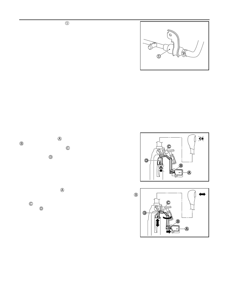
• The heater thermostat is installed to front part of transaxle
assembly.
• The heater thermostat open and close with set temperature.
SHIFT LOCK SYSTEM
SHIFT LOCK SYSTEM : System Description
INFOID:0000000009759343
• The shift lock is the mechanism provided to prevent quick start of a vehicle by incorrect operation of a drive
when the selector lever is in “P” position.
• Selector lever can be shifted from the “P” position to another position when the following conditions are sat-
isfied.
- Ignition switch is ON.
- Stop lamp switch is ON (brake pedal is depressed)
- Press the selector button.
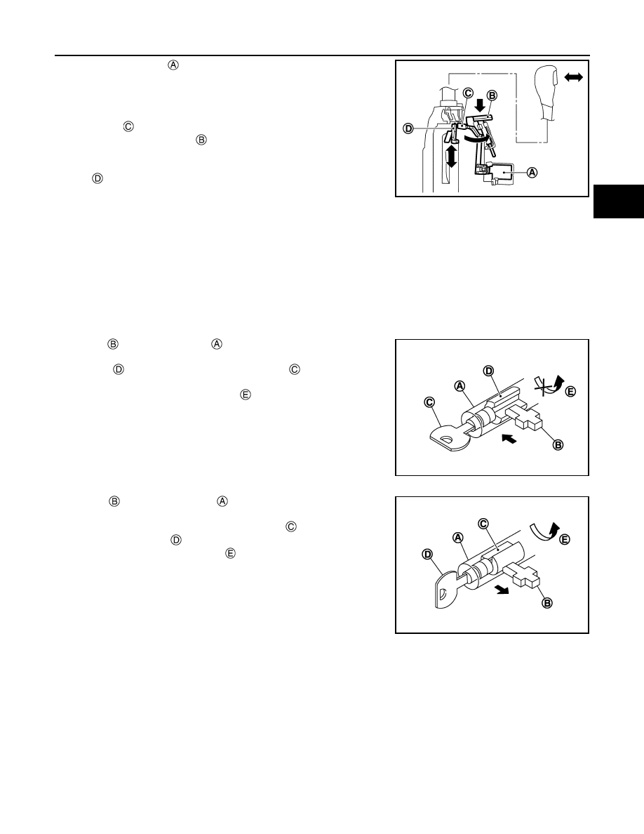
SHIFT LOCK OPERATION AT P POSITION
When brake pedal is not depressed (no selector operation allowed)
When the brake pedal is not depressed with the ignition switch ON,
the shift lock solenoid is OFF (not energized) and the solenoid rod
is extended with spring.
The connecting lock lever is located at the position shown in the
figure when the solenoid rod is extended. It prevents the movement
of the detent rod . The selector lever cannot be shifted from the “P”
position for this reason.
When brake pedal is depressed (selector lever operation allowed)
The shift lock solenoid is turned ON (energized) when the brake
pedal is depressed with the ignition switch ON. The solenoid rod
is compressed with the electromagnetic force. The connecting lock
lever rotates when the solenoid rod is compressed. Therefore, the
detent rod can be moved. The selector lever can be shifted to
other positions for this reason.
P POSITION HOLD MECHANISM (IGNITION SWITCH LOCK)
JSDIA3652ZZ
JSDIA2830ZZ
JSDIA2831ZZ
STRUCTURE AND OPERATION
TM-91
< SYSTEM DESCRIPTION >
[CVT: RE0F11A]
C
E
F
G
H
I
J
K
L
M
A
B
TM
N
O
P
The shift lock solenoid is not energized when the ignition switch is
in any position other than ON. The shift mechanism is locked and “P”
position is held. The operation cannot be performed from “P” position
if the brake pedal is depressed with the ignition switch ON when the
operation system of shift lock solenoid is malfunctioning. However,
the lock lever is forcibly rotated and the shift lock is released when
the shift lock release button is pressed from above. The selector
operation from “P” position can be performed.
CAUTION:
Use the shift lock release button only when the selector lever cannot be operated even if the brake
pedal is depressed with the ignition switch ON.
KEY LOCK SYSTEM
KEY LOCK SYSTEM : System Description
INFOID:0000000009759344
KEY LOCK MECHANISM
The key is not set to LOCK when the selector lever is not selected to P position. This prevents the key from
being removed from the key cylinder.
Key lock status
The slider in the key cylinder is moved to the left side of the fig-
ure when the selector lever is in any position other than “P” position.
The rotator that rotates together with the key cannot be rotated
for this reason. The key cannot be removed from the key cylinder
because it cannot be turned to LOCK .
Key unlock status
The slider in the key cylinder is moved to the right side of the
figure when the selector lever is in “P” position and the finger is
removed from the selector button. The rotator can be rotated for
this reason. The key can be removed from the key cylinder
because it can be turned to LOCK .
: Detent rod
JSDIA2832ZZ
JPDIA0108ZZ
JPDIA0109ZZ
Нет комментариевНе стесняйтесь поделиться с нами вашим ценным мнением.
Текст