Nissan Sentra. Instruction — part 895
TM-216
< DTC/CIRCUIT DIAGNOSIS >
[CVT: RE0F11A]
P099C SHIFT SOLENOID G
P099C SHIFT SOLENOID G
DTC Logic
INFOID:0000000009759465
DTC DETECTION LOGIC
DTC CONFIRMATION PROCEDURE
1.
PREPARATION BEFORE WORK
If another “DTC CONFIRMATION PROCEDURE” occurs just before, turn ignition switch OFF and wait for at
least 10 seconds, then perform the next test.
>> GO TO 2.
2.
CHECK DTC DETECTION
1. Start the engine and wait for 5 seconds or more
2. Check the first trip DTC.
Is “P099C” detected?
YES
>> Go to
NO
>> INSPECTION END
Diagnosis Procedure
INFOID:0000000009759466
1.
CHECK CIRCUIT BETWEEN TCM AND CVT UNIT
1. Turn ignition switch OFF.
2. Disconnect TCM connector and CVT unit connector.
3. Check continuity between TCM harness connector terminal and CVT unit harness connector terminal.
Is the inspection result normal?
YES
>> GO TO 2.
NO
>> Repair or replace malfunctioning parts.
2.
CHECK HIGH CLUTCH & REVERSE BRAKE SOLENOID VALVE
Check high clutch & reverse brake solenoid valve. Refer to
TM-216, "Component Inspection"
.
Is the inspection result normal?
YES >> Check
intermittent incident. Refer to
GI-39, "Intermittent Incident"
.
NO
>> Repair or replace malfunctioning parts.
Component Inspection
INFOID:0000000009759467
1.
CHECK HIGH CLUTCH & REVERSE BRAKE SOLENOID VALVE
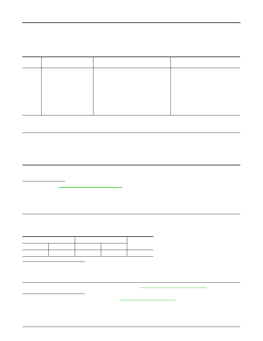
DTC
CONSULT screen terms
(Trouble diagnosis content)
DTC detection condition
Possible causes
P099C
SHIFT SOLENOID G
(Shift Solenoid G Control Cir-
cuit High)
The TCM high clutch & reverse brake solenoid
valve current monitor reading is 200 mA or
less continuously for 200 msec or more under
the following diagnosis conditions:
• Diagnosis conditions
- Solenoid valve output current: 750 mA or
more
- GND short diagnosis of the solenoid valve
circuit is not satisfied.
- TCM power supply voltage: More than 11 V
• Harness or connector
(High clutch & reverse brake solenoid
valve circuit is open or shorted to pow-
er supply)
• High clutch & reverse brake solenoid
valve
TCM
CVT unit
Continuity
Connector
Terminal
Connector
Terminal
F23
37
F46
23
Existed

P099C SHIFT SOLENOID G
TM-217
< DTC/CIRCUIT DIAGNOSIS >
[CVT: RE0F11A]
C
E
F
G
H
I
J
K
L
M
A
B
TM
N
O
P
Check resistance between CVT unit connector terminal and ground.
Is the inspection result normal?
YES
>> INSPECTION END
NO
>> There is a malfunction of high & reverse brake solenoid valve. Replace transaxle assembly. Refer
to
TM-283, "Removal and Installation"
.
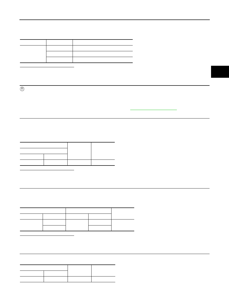
CVT unit
—
Condition
Resistance
(Approx.)
Terminal
23
Ground
CVT fluid temperature: 20
°C (68°F)
5.3
Ω
CVT fluid temperature: 50
°C (122°F)
6.0
Ω
CVT fluid temperature: 80
°C (176°F)
6.7
Ω

TM-218
< DTC/CIRCUIT DIAGNOSIS >
[CVT: RE0F11A]
P1586 G SENSOR
P1586 G SENSOR
DTC Logic
INFOID:0000000009759468
DTC DETECTION LOGIC
NOTE:
DC stands for “DRIVING CYCLE” and indicates a series of driving cycle of “Ignition switch OFF
→ ON → driv-
ing
→ OFF”.
DTC CONFIRMATION PROCEDURE
CAUTION:
Be careful of the driving speed.
1.
PREPARATION BEFORE WORK
If another “DTC CONFIRMATION PROCEDURE” occurs just before, turn ignition switch OFF and wait for at
least 10 seconds, then perform the next test.
>> GO TO 2.
2.
CHECK DTC DETECTION
With CONSULT
1. Start the engine.
2. Drive the vehicle for 10 seconds or more.
3. Stop the vehicle.
CAUTION:
Never stop the engine.
4. Repeat step 2 through 3.
5. Check the DTC.
Is “P1586” detected?
YES
>> Go to
NO
>> INSPECTION END
Diagnosis Procedure
INFOID:0000000009759469
1.
CHECK G SENSOR SIGNAL
With CONSULT
1. Park the vehicle on a level surface.
2. Turn ignition switch ON.
DTC
CONSULT screen terms
(Trouble diagnosis content)
DTC detection condition
Possible causes
P1586
G Sensor
(Gravity Sensor Circuit)
When the following diagnosis conditions are
satisfied and the detection conditions are sat-
isfied twice in the same DC:
• Diagnosis conditions
- While driving
- TCM power supply voltage: More than 11 V
• Detection condition
- The G sensor detection voltage is 0.7 V or
less continuously for 5 seconds or more.
• Harness or connector
(G sensor circuit)
• G sensor
When the following diagnosis conditions are
satisfied and the detection conditions are sat-
isfied twice in the same DC:
• Diagnosis conditions
- While driving
- TCM power supply voltage: More than 11 V
• Detection condition
- The G sensor detection voltage is 3.2 V or
more continuously for 5 seconds or more.
P1586 G SENSOR
TM-219
< DTC/CIRCUIT DIAGNOSIS >
[CVT: RE0F11A]
C
E
F
G
H
I
J
K
L
M
A
B
TM
N
O
P
3. Select “Data Monitor” in “TRANSMISSION”.
4. Select “G SEN SLOPE”.
5. Swing the vehicle and check if the value varies between
−40.45% and 40.45%.
Is the inspection result normal?
YES
>> GO TO 2.
NO
>> GO TO 3.
2.
CALIBRATION OF G SENSOR (PART 1)
With CONSULT
1. Select “Self Diagnostic Results” in “TRANSMISSION”.
2. Touch “Erase”.
>> Perform “CALIBRATION OF G SENSOR”. Refer to
3.
CHECK SENSOR POWER SUPPLY
1. Turn ignition switch OFF.
2. Disconnect G sensor connector.
3. Turn ignition switch ON.
4. Check voltage between G sensor harness connector terminal and ground.
Is the inspection result normal?
YES
>> GO TO 4.
NO
>> GO TO 8.
4.
CHECK CIRCUIT BETWEEN TCM AND G SENSOR (PART 1)
1. Turn ignition switch OFF.
2. Disconnect TCM connector.
3. Check continuity between TCM harness connector terminals and G sensor harness connector terminals.
Is the inspection result normal?
YES
>> GO TO 5.
NO
>> Repair or replace malfunctioning parts.
5.
CHECK CIRCUIT BETWEEN TCM AND G SENSOR (PART 2)
Check continuity between TCM harness connector terminal and ground.
Monitor item
Condition
Standard
G SEN SLOPE
Flat road
0%
Uphill
Positive value (Maximum 40.45%)
Downhill
Negative value (Minimum
−40.45%)
+
-
Voltage
(Approx.)
G sensor
Connector
Terminal
B89
3
Ground
5.0 V
TCM
G sensor
Continuity
Connector
Terminal
Connector
Terminal
F23
11
B89
2
Existed
14
1
TCM
—
Continuity
Connector
Terminal
F23
14
Ground
Not existed
Нет комментариевНе стесняйтесь поделиться с нами вашим ценным мнением.
Текст