Nissan Sentra. Instruction — part 155
COMPONENT PARTS
BRC-7
< SYSTEM DESCRIPTION >
[VDC/TCS/ABS]
C
D
E
G
H
I
J
K
L
M
A
B
BRC
N
O
P
SYSTEM DESCRIPTION
COMPONENT PARTS
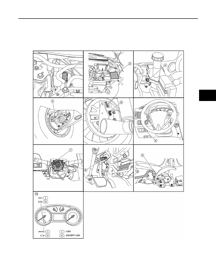
Component Parts Location
INFOID:0000000009757807
1.
ABS actuator and electric unit (con-
trol unit)
2.
IPDM E/R
3.
Brake fluid level switch
4.
Front wheel sensor LH (RH similar)
5.
Rear wheel sensor LH (RH similar)
6.
VDC OFF switch
ALFIA0342ZZ
BRC-8
< SYSTEM DESCRIPTION >
[VDC/TCS/ABS]
COMPONENT PARTS
Component Description
INFOID:0000000009757808
ABS Actuator and Electric Unit (Control Unit)
INFOID:0000000009757809
Electric unit (control unit) is integrated with actuator and comprehensively controls VDC function, TCS func-
tion, ABS function and EBD function.
ELECTRIC UNIT (CONTROL UNIT)
• Brake fluid pressure is controlled according to signals from each sensor.
• If malfunction is detected, the system enters fail-safe mode.
ACTUATOR
The following components are integrated with ABS actuator.
Pump
Returns the brake fluid reserved in reservoir to master cylinder by reducing pressure.
Motor
Activates the pump according to signals from ABS actuator and electric unit (control unit).
Motor Relay
Operates the motor ON/OFF according to signals from ABS actuator and electric unit (control unit).
Actuator Relay (Main Relay)
Operates each valve ON/OFF according to signals from ABS actuator and electric unit (control unit).
ABS IN Valve
Switches the fluid pressure line to increase or hold according to signals from control unit.
ABS OUT Valve
Switches the fluid pressure line to increase, hold or decrease according to signals from control unit.
Cut Valve 1, Cut Valve 2
Shuts off the ordinary brake line from master cylinder, when VDC function and TCS function are activated.
Suction Valve 1, Suction Valve 2
7.
Steering angle sensor
(view with steering wheel removed)
8.
Stop lamp switch
9.
Parking brake switch
10. Combination meter
Component
Reference/Function
ABS actuator and electric unit (control unit)
BRC-8, "ABS Actuator and Electric Unit (Control Unit)"
Wheel sensor
BRC-9, "Wheel Sensor and Sensor Rotor"
Stop lamp switch
Steering angle sensor
BRC-9, "Steering Angle Sensor"
VDC OFF switch
Brake fluid level switch
BRC-9, "Brake Fluid Level Switch"
Parking brake switch
ABS warning lamp
BRC-11, "VDC/TCS/ABS : System Description"
Brake warning lamp
VDC OFF indicator lamp
SLIP indicator lamp
ECM
Transmits the following signals to ABS actuator and electric unit (control unit) via CAN
communication.
• Accelerator pedal position signal
• Engine speed signal
• Target throttle position signal
TCM
Transmits the current gear position signal to ABS actuator and electric unit (control
unit) via CAN communication.
COMPONENT PARTS
BRC-9
< SYSTEM DESCRIPTION >
[VDC/TCS/ABS]
C
D
E
G
H
I
J
K
L
M
A
B
BRC
N
O
P
Supplies the brake fluid from master cylinder to the pump, when VDC function and TCS function are activated.
Return Check Valve
Returns the brake fluid from brake caliper and wheel cylinder to master cylinder by bypassing orifice of each
valve when brake is released.
Reservoir
Temporarily reserves the brake fluid drained from brake caliper, so that pressure efficiently decreases when
decreasing pressure of brake caliper and wheel cylinder.
Yaw rate/side/decel G sensor
Calculates the following information that affects the vehicle.
• Vehicle rotation angular velocity (yaw rate signal)
• Vehicle lateral acceleration (side G signal) and longitudinal acceleration (decel G signal)
Pressure Sensor
Detects the brake fluid pressure.
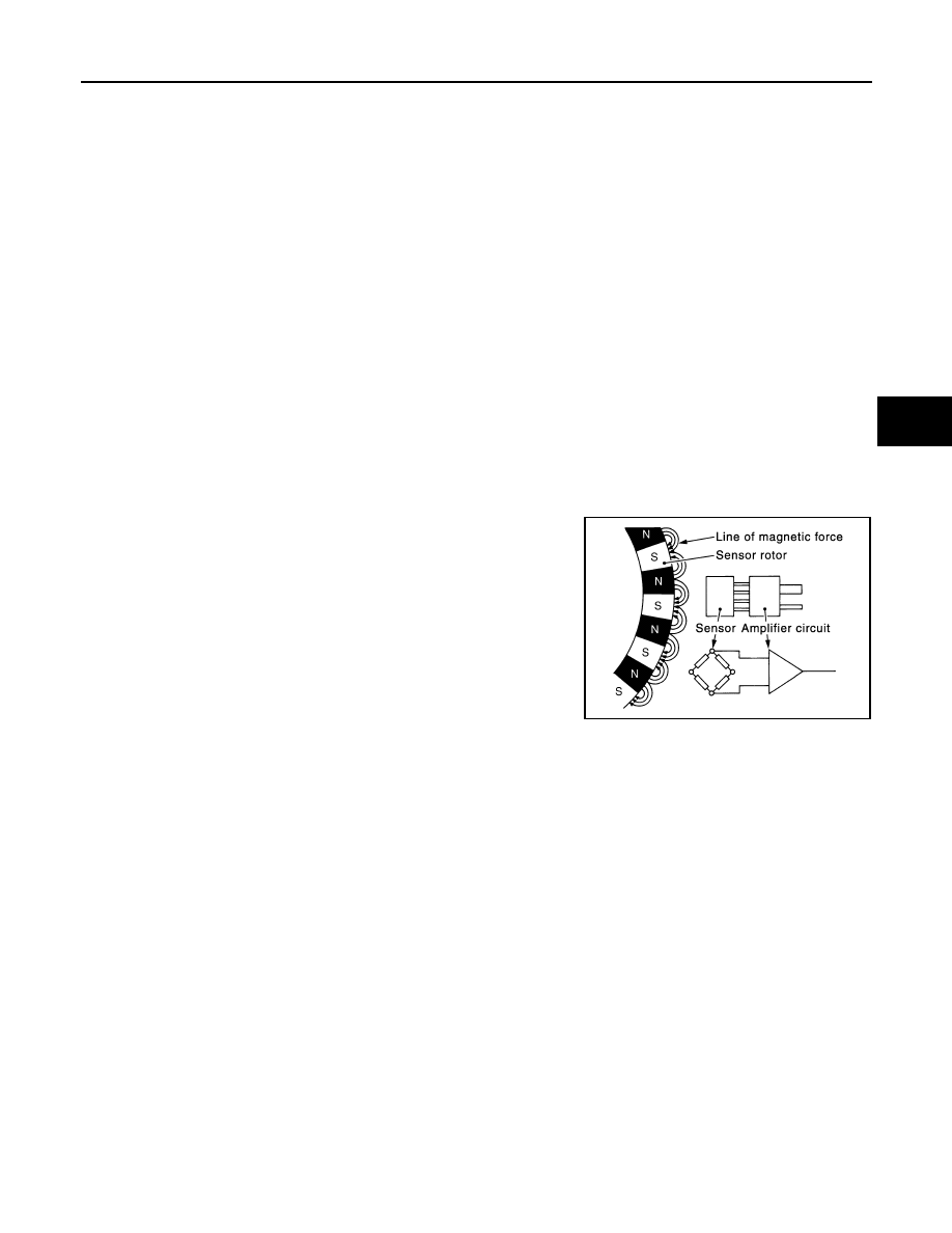
Wheel Sensor and Sensor Rotor
INFOID:0000000009757810
NOTE:
• Wheel sensor of front wheel is installed on steering knuckle.
• Sensor rotor of front wheel is integrated in wheel hub assembly.
• Wheel sensor of rear wheel is installed on back plate of rear brake.
• Sensor rotor of rear wheel is installed on rear brake drum.
• Never measure resistance and voltage value using a tester because sensor is active sensor.
• Downsize and weight reduction is aimed. IC for detection portion
and magnet for sensor rotor are adopted.
• Power supply is supplied to detection portion so that magnetic field
line is read. Magnetic field that is detected is converted to current
signal.
• When sensor rotor rotates, magnetic field changes. Magnetic field
change is converted to current signals (rectangular wave) and is
transmitted to ABS actuator and electric unit (control unit). Change
of magnetic field is proportional to wheel speed.
Stop Lamp Switch
INFOID:0000000009757811
Detects the operation status of brake pedal and transmits converted electric signal to ABS actuator and elec-
tric unit (control unit).
Steering Angle Sensor
INFOID:0000000009757812
Detects the following information and transmits steering angle signal to ABS actuator and electric unit (control
unit) via CAN communication.
• Steering wheel rotation amount
• Steering wheel rotation angular velocity
• Steering wheel rotation direction
Brake Fluid Level Switch
INFOID:0000000009757813
Detects the brake fluid level in reservoir tank and transmits converted electric signal from combination meter to
ABS actuator and electric unit (control unit) via CAN communication.
Parking Brake Switch
INFOID:0000000009757814
Detects the operation status of parking brake switch and transmits converted electric signal from combination
meter to ABS actuator and electric unit (control unit) via CAN communication.
JPFIC0131GB
BRC-10
< SYSTEM DESCRIPTION >
[VDC/TCS/ABS]
COMPONENT PARTS
VDC OFF Switch
INFOID:0000000009757815
• Non-operational status or standby status of VDC and TCS functions can be selected using VDC OFF switch.
VDC OFF indicator lamp indicates the operation status of function. (ON: Non-operational status, OFF:
Standby status)
• VDC OFF indicator lamp turns OFF (standby status) when the engine is started again after it is stopped once
while VDC OFF indicator lamp is ON (non-operational status).
Нет комментариевНе стесняйтесь поделиться с нами вашим ценным мнением.
Текст