Nissan Sentra. Instruction — part 156
SYSTEM
BRC-11
< SYSTEM DESCRIPTION >
[VDC/TCS/ABS]
C
D
E
G
H
I
J
K
L
M
A
B
BRC
N
O
P
SYSTEM
VDC/TCS/ABS
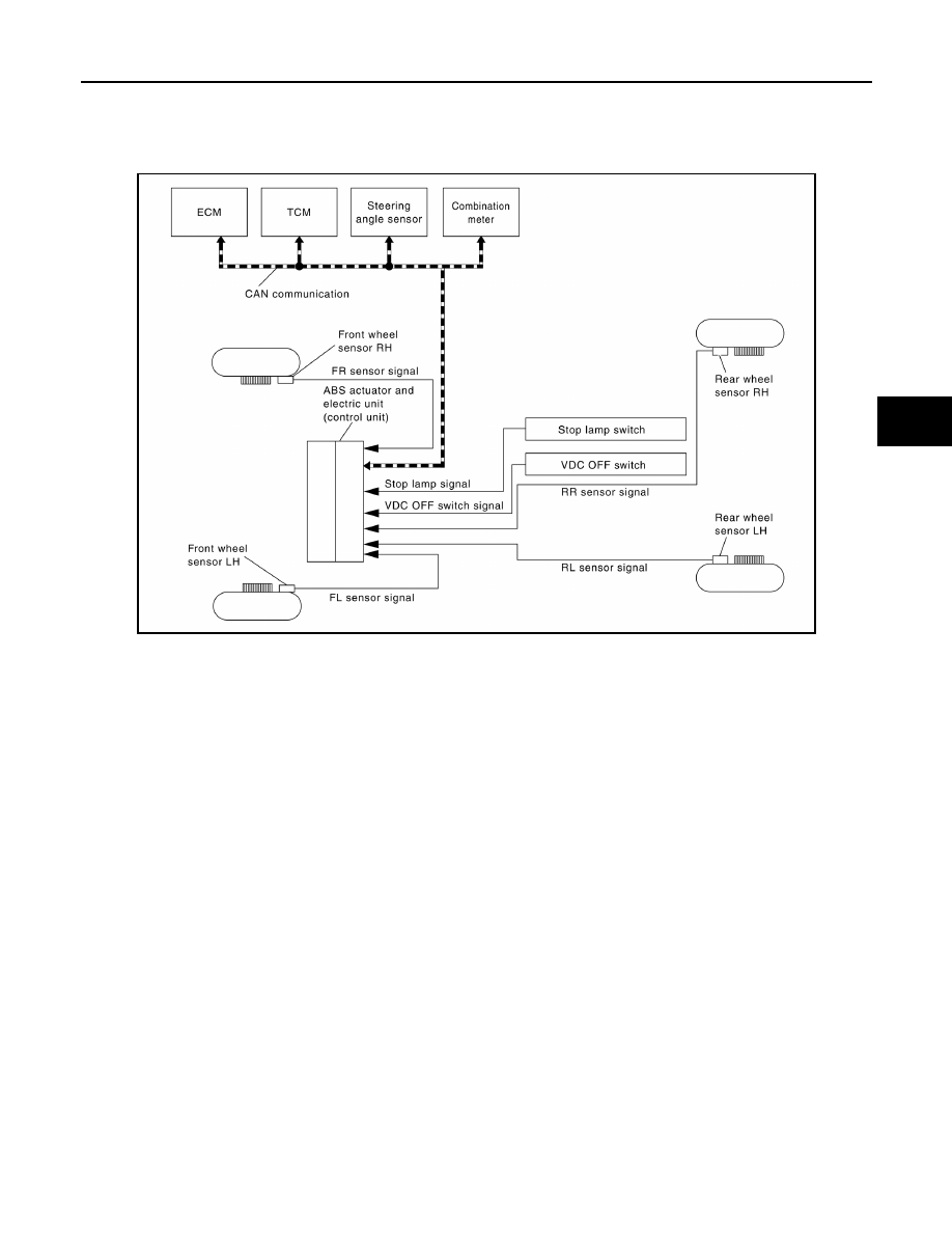
VDC/TCS/ABS : System Diagram
INFOID:0000000009757816
VDC/TCS/ABS : System Description
INFOID:0000000009757817
• The system switches fluid pressure of each brake caliper and each wheel cylinder to increase, to hold, or to
decrease according to signals from control unit in ABS actuator and electric unit (control unit). This control
system is applied to VDC, TCS, ABS and EBD functions.
• Fail-safe function is available for each function and is activated by each function when system malfunction
occurs.
INPUT SIGNAL AND OUTPUT SIGNAL
Major signal transmission between each unit via communication lines is shown in the following table.
ALFIA0331GB
BRC-12
< SYSTEM DESCRIPTION >
[VDC/TCS/ABS]
SYSTEM
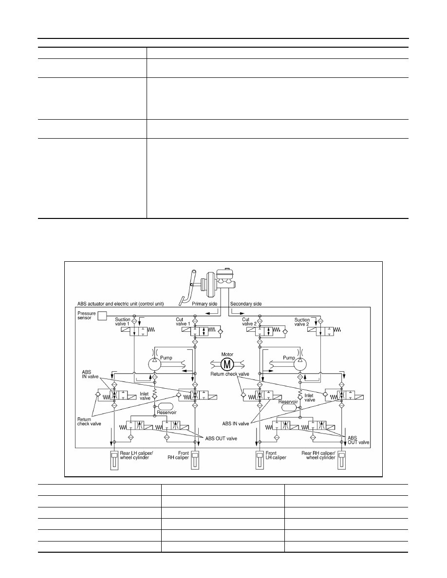
VALVE OPERATION (VDC AND TCS FUNCTIONS)
The control unit built in the ABS actuator and electric unit (control unit) controls fluid pressure of the brake cal-
ipers by operating each valve.
VDC and TCS Functions are Operating (Pressure Increases)
Component
Signal description
Steering angle sensor
Transmits the steering angle sensor signal to ABS actuator and electric unit (control unit) via
CAN communication.
ECM
Transmits the following signals to ABS actuator and electric unit (control unit) via CAN commu-
nication.
• Accelerator pedal position signal
• Engine speed signal
• Target throttle position signal
TCM
Transmits the current gear position signal to ABS actuator and electric unit (control unit) via
CAN communication.
Combination meter
Transmits the following signals to ABS actuator and electric unit (control unit) via CAN commu-
nication.
• Brake fluid level switch signal
• Parking brake switch signal
Receives the following signals from ABS actuator and electric unit (control unit) via CAN com-
munication.
• ABS warning lamp signal
• Brake warning lamp signal
• VDC OFF indicator lamp signal
• SLIP indicator lamp signal
ALFIA0332GB
Name
Not activated
Pressure increases
Cut valve 1
Power supply is not supplied (open)
Power supply is supplied (close)
Cut valve 2
Power supply is not supplied (open)
Power supply is supplied (close)
Suction valve 1
Power supply is not supplied (close)
Power supply is supplied (open)
Suction valve 2
Power supply is not supplied (close)
Power supply is supplied (open)
ABS IN valve
Power supply is not supplied (open)
Power supply is not supplied (open)
SYSTEM
BRC-13
< SYSTEM DESCRIPTION >
[VDC/TCS/ABS]
C
D
E
G
H
I
J
K
L
M
A
B
BRC
N
O
P
Front RH brake caliper
• Brake fluid is conveyed to the pump from the master cylinder through suction valve 1 and is pressurized by
the pump operation. The pressurized brake fluid is supplied to the front RH brake caliper through the ABS IN
valve. For the left caliper, brake fluid pressure is maintained because the pressurization is unnecessary. The
pressurization for the left caliper is controlled separately from the right caliper.
Front LH brake caliper
• Brake fluid is conveyed to the pump from the master cylinder through suction valve 2 and is pressurized by
the pump operation. The pressurized brake fluid is supplied to the front LH brake caliper through the ABS IN
valve. For the right caliper, brake fluid pressure is maintained because the pressurization is unnecessary.
The pressurization for the right caliper is controlled separately from the left caliper.
Rear RH brake caliper/wheel cylinder
• Brake fluid is conveyed to the pump from the master cylinder through suction valve 2 and is pressurized by
the pump operation. The pressurized brake fluid is supplied to the rear RH brake caliper/wheel cylinder
through the ABS IN valve. For the left caliper/wheel cylinder, brake fluid pressure is maintained because the
pressurization is unnecessary. The pressurization for the left caliper/wheel cylinder is controlled separately
from the right caliper/wheel cylinder.
Rear LH brake caliper/wheel cylinder
• Brake fluid is conveyed to the pump from the master cylinder through suction valve 1 and is pressurized by
the pump operation. The pressurized brake fluid is supplied to the rear LH brake caliper/wheel cylinder
through the ABS IN valve. For the right caliper/wheel cylinder, brake fluid pressure is maintained because
the pressurization is unnecessary. The pressurization for the right caliper/wheel cylinder is controlled sepa-
rately from the left caliper/wheel cylinder.
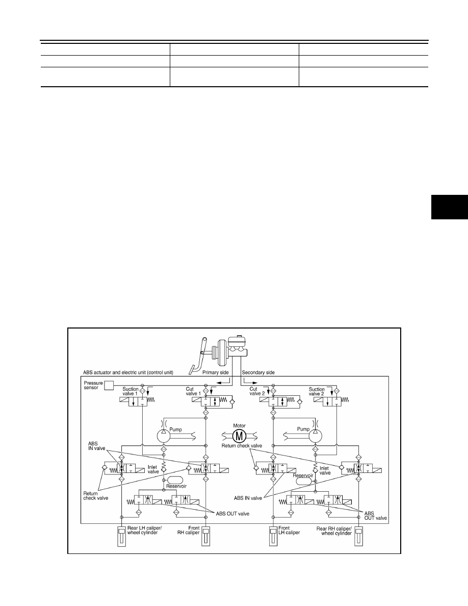
VDC and TCS Functions Start Operating (Pressure Holds)
ABS OUT valve
Power supply is not supplied (close)
Power supply is not supplied (close)
Each brake caliper and each wheel cylinder
(fluid pressure)
—
Pressure increases
Name
Not activated
Pressure increases
ALFIA0333GB
BRC-14
< SYSTEM DESCRIPTION >
[VDC/TCS/ABS]
SYSTEM
Front RH brake caliper
• Since the cut valve 1 and the suction valve 1 are closed, the front RH brake caliper, master cylinder, and res-
ervoir are blocked. This maintains fluid pressure applied on the front RH brake caliper. The pressurization for
the left caliper is controlled separately from the right caliper.
Front LH brake caliper
• Since the cut valve 2 and the suction valve 2 are closed, the front LH brake caliper, master cylinder, and res-
ervoir are blocked. This maintains fluid pressure applied on the front LH brake caliper. The pressurization for
the right caliper is controlled separately from the left caliper.
Rear RH brake caliper/wheel cylinder
• Since the cut valve 2 and the suction valve 2 are closed, the rear RH brake caliper/wheel cylinder, master
cylinder, and reservoir are blocked. This maintains fluid pressure applied on the rear RH brake caliper/wheel
cylinder. The pressurization for the left caliper/wheel cylinder is controlled separately from the right caliper/
wheel cylinder.
Rear LH brake caliper/wheel cylinder
• Since the cut valve 1 and the suction valve 1 are closed, the rear LH brake caliper/wheel cylinder, master
cylinder, and reservoir are blocked. This maintains fluid pressure applied on the rear LH brake caliper/wheel
cylinder. The pressurization for the right caliper/wheel cylinder is controlled separately from the left caliper/
wheel cylinder.
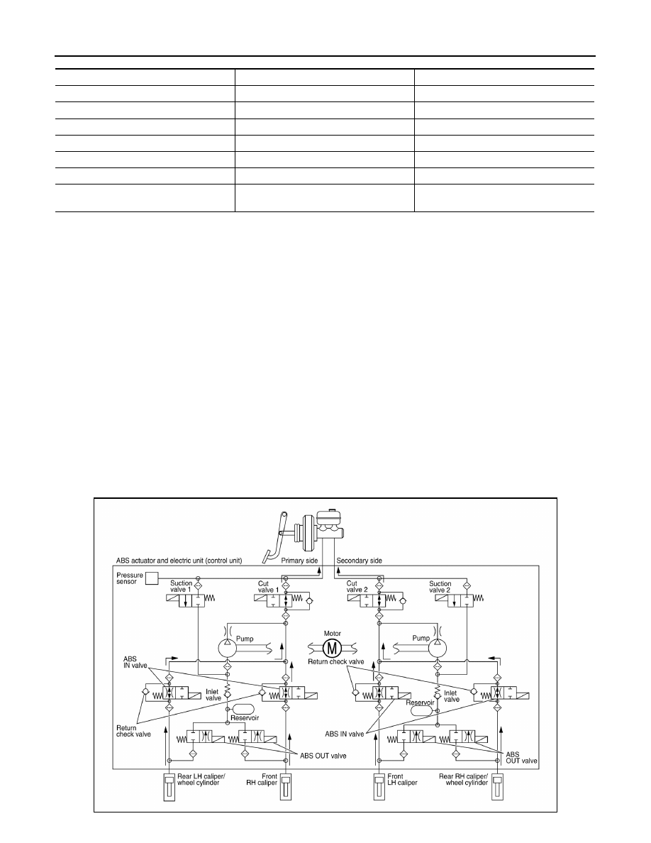
VDC and TCS Functions Operating (Pressure Decreases)
Name
Not activated
Pressure holds
Cut valve 1
Power supply is not supplied (open)
Power supply is supplied (close)
Cut valve 2
Power supply is not supplied (open)
Power supply is supplied (close)
Suction valve 1
Power supply is not supplied (close)
Power supply is not supplied (close)
Suction valve 2
Power supply is not supplied (close)
Power supply is not supplied (close)
ABS IN valve
Power supply is not supplied (open)
Power supply is not supplied (open)
ABS OUT valve
Power supply is not supplied (close)
Power supply is not supplied (close)
Each brake caliper and each wheel cylinder
(fluid pressure)
—
Pressure holds
ALFIA0334GB
Нет комментариевНе стесняйтесь поделиться с нами вашим ценным мнением.
Текст