Nissan Sentra. Instruction — part 640
MWI-6
< SYSTEM DESCRIPTION >
COMPONENT PARTS
METER SYSTEM : Component Description
INFOID:0000000009758232
AWNIA3363ZZ
1.
ABS actuator and electric unit (control
unit)
2.
Combination meter
3.
CVT shift selector (with CVT)
(O/D OFF switch)
4.
Air bag diagnosis sensor unit
(view with center console assembly re-
moved)
5.
Parking brake switch
(view with center console removed)
6.
Fuel level sensor unit and fuel pump
(view with fuel pump inspection cover
removed)
7.
Seat belt buckle switch LH
(RH similar)
8.
Front door switch LH
(RH similar)
9.
BCM
(view with instrument panel removed)
10. Power steering control module
(view with steering column assembly
removed)
11. Brake fluid level switch
12. TCM (with CVT)
13. ECM
14. Engine oil pressure sensor
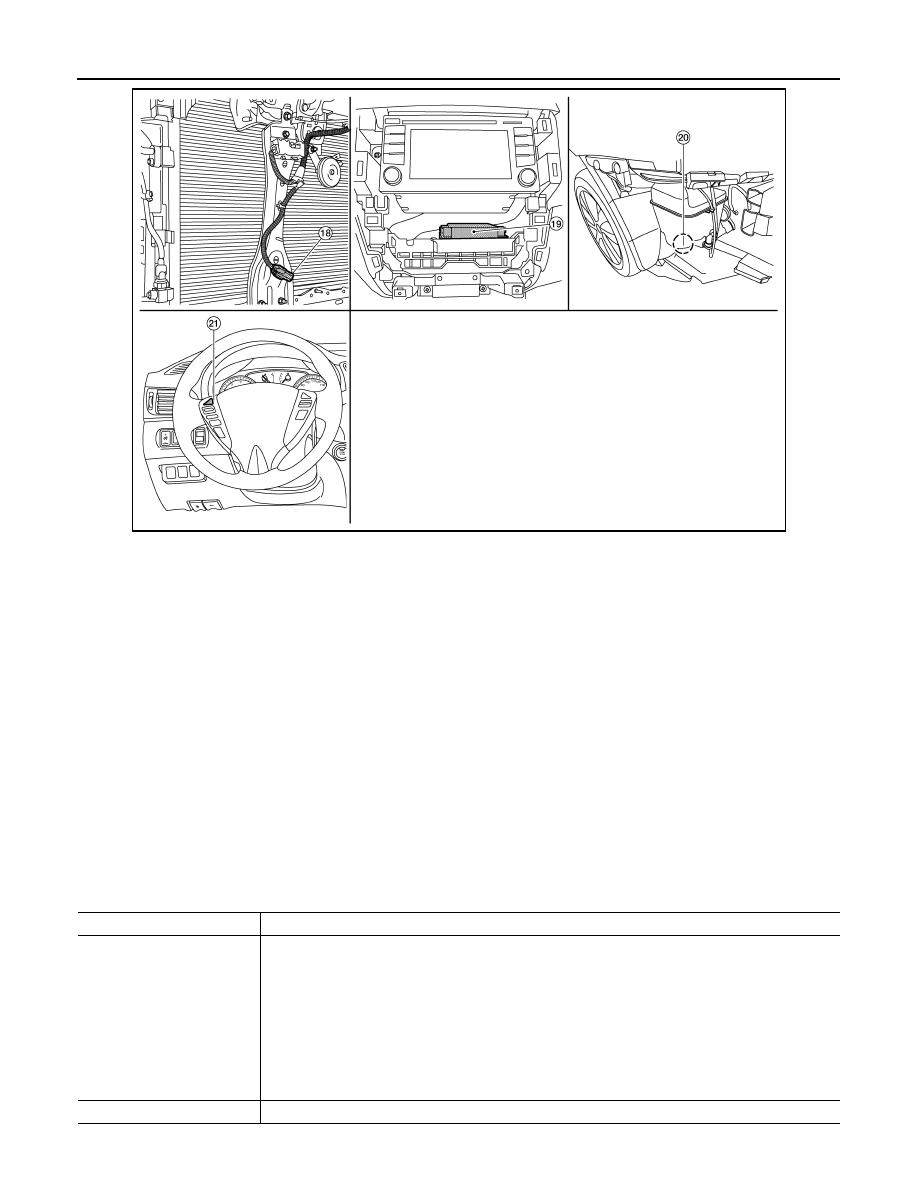
15. Illumination control switch
16. ECO mode switch (with CVT)
17. Sport mode switch (with CVT)
18. Ambient sensor
19. A/C auto amp.
(with auto A/C)
(view with A/C switch assembly re-
moved)
20. Washer fluid level switch
(view with front fascia removed)
21. Steering switch
Unit
Description
Combination meter
Controls the following with the signals received from each unit via CAN communication and the signals
from switches and sensors:
• Speedometer
• Tachometer
• Engine coolant temperature gauge
• Fuel gauge
• Warning lamps
• Indicator lamps
• Meter illumination control
• Information display
Steering switch
Transmits the meter control switch signal to the combination meter.

MWI
COMPONENT PARTS
MWI-7
< SYSTEM DESCRIPTION >
C
D
E
F
G
H
I
J
K
L
M
B
A
O
P
Illumination control switch
Transmits the following signals to the combination meter:
• Illumination control switch signal (+)
• Illumination control switch signal (
−)
ECM
Transmits the following signals to the combination meter via CAN communication:
• Engine speed signal
• Engine coolant temperature signal
• Engine oil pressure warning signal
• Fuel consumption monitor signal
ABS actuator and electric unit
(control unit)
Transmits the vehicle speed signal to the combination meter via CAN communication.
Power steering control module Transmits the EPS signal to the combination meter via CAN communication.
BCM
Transmits the following signals to the combination meter via CAN communication:
• Position light request signal
• Low tire pressure warning lamp signal
• Door switch signal
• Trunk lamp switch signal
TCM
Receives the O/D OFF switch signal from the combination meter via CAN communication.
Transmits the following signals to the combination meter via CAN communication:
• O/D OFF indicator request signal
• CVT shift selector position signal
CVT shift selector switch
(O/D OFF switch)
Transmits the O/D OFF switch signal to the combination meter
Fuel level sensor unit
Transmits the fuel level sensor signal to the combination meter.
Seat belt buckle switch LH
(RH similar)
Transmits the seat belt buckle switch LH signal to the combination meter.
Air bag diagnosis sensor unit
Transmits the following signals to the combination meter:
• Seat belt buckle switch RH signal
• Air bag warning indicator
Engine oil pressure sensor
Transmits the engine oil pressure sensor signal to the ECM.
Ambient sensor
Transmits the ambient sensor signal to the combination meter (without auto a/c).
Transmits the ambient sensor signal to the A/C auto amp. (with auto a/c).
A/C auto amp.
• Receives the ambient sensor signal from the ambient sensor (with auto a/c).
• Transmits the ambient sensor signal to the combination meter via CAN communication.
Parking brake switch
Transmits the parking brake switch signal to the combination meter.
Washer fluid level switch
Transmits the washer fluid level switch signal to the combination meter.
Brake fluid level switch
Transmits the brake fluid level switch signal to the combination meter.
Unit
Description
MWI-8
< SYSTEM DESCRIPTION >
SYSTEM
SYSTEM
METER SYSTEM
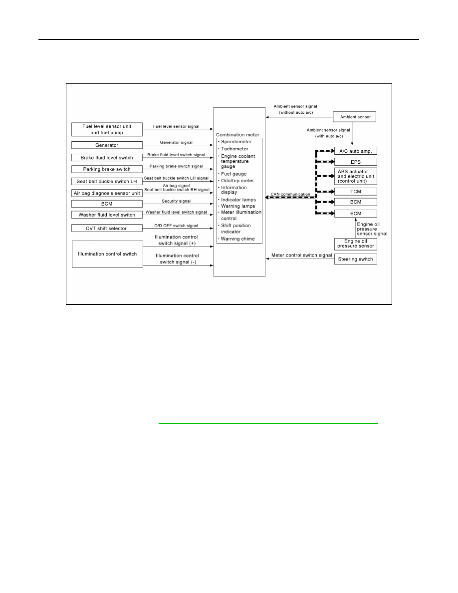
METER SYSTEM : System Diagram
INFOID:0000000009758233
METER SYSTEM : System Description
INFOID:0000000009758234
COMBINATION METER
• The combination meter receives signals from switches, sensors and modules to control the following func-
tions:
- Speedometer/tachometer
- Warning lamps
- Indicator lamps
- Meter illumination control
- Information display
• The combination meter has an integrated buzzer that is activated when it receives a signal from the BCM via
CAN communication. Refer to
WCS-6, "WARNING CHIME SYSTEM : System Description"
for further
details.
• The combination meter includes an on-board diagnosis function.
• The combination meter can be diagnosed with CONSULT.
AWNIA2857GB
MWI
SYSTEM
MWI-9
< SYSTEM DESCRIPTION >
C
D
E
F
G
H
I
J
K
L
M
B
A
O
P
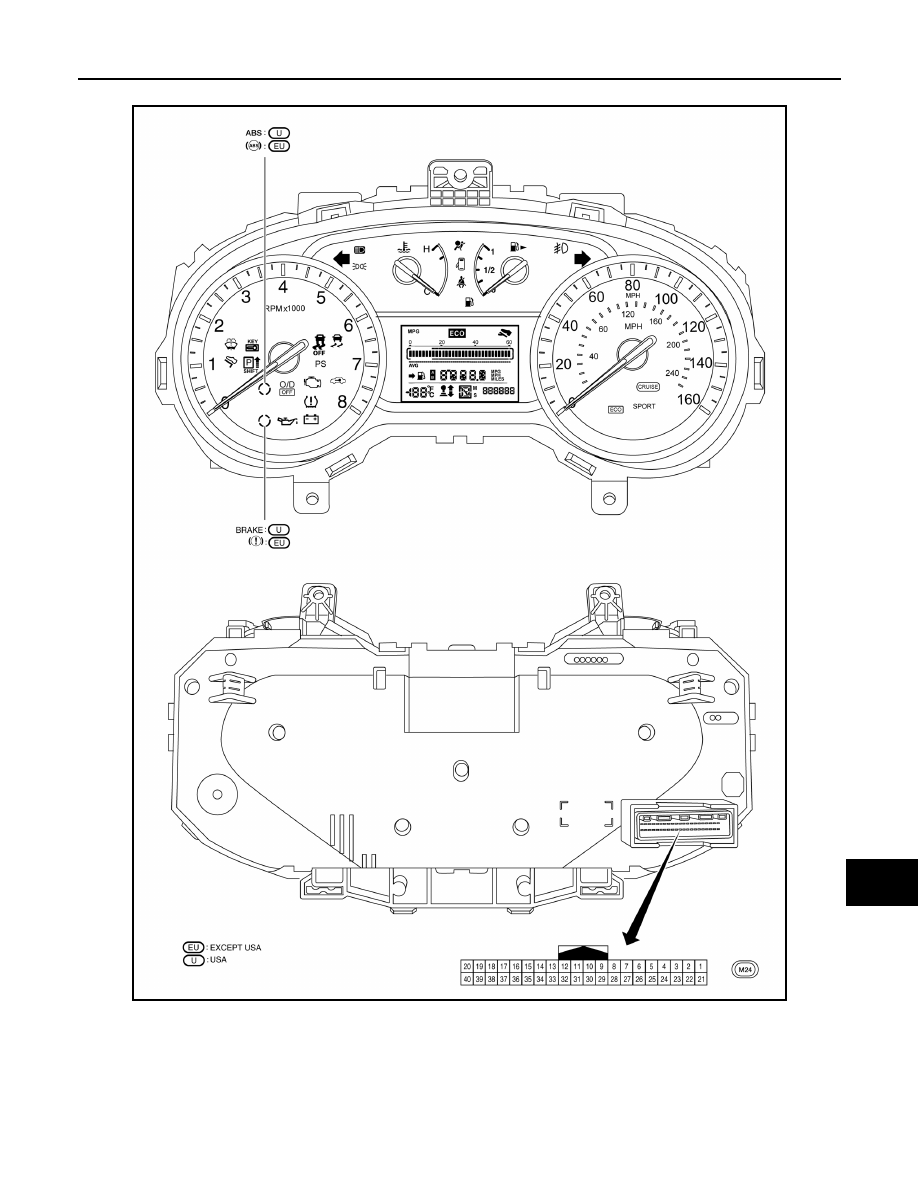
METER SYSTEM : Arrangement of Combination Meter
INFOID:0000000009758235
METER SYSTEM : Fail-Safe
INFOID:0000000009758236
The combination meter activates the fail-safe control if CAN communication with each unit is malfunctioning.
AWNIA2704GB
Нет комментариевНе стесняйтесь поделиться с нами вашим ценным мнением.
Текст