Nissan Sentra. Instruction — part 638
DOOR MIRROR
MIR-19
< REMOVAL AND INSTALLATION >
C
D
E
F
G
H
I
J
K
M
A
B
MIR
N
O
P
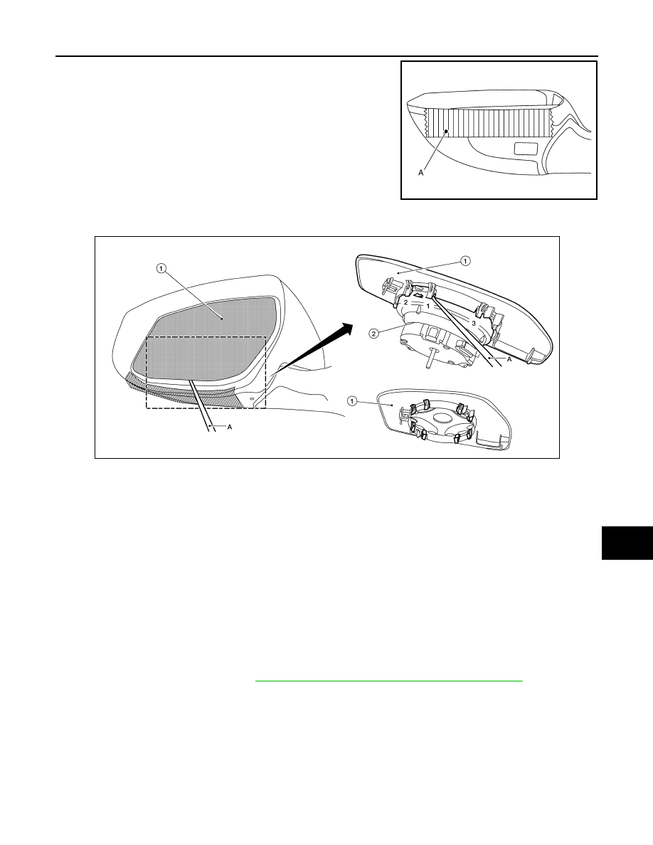
1. Put a strip of protective tape (A) on housing assembly.
2. Insert a suitable tool (A) into the recess at lower side between glass mirror (1) and actuator (2), and push
up pawls to remove glass mirror lower side in the order shown.
3. Insert a suitable tool at (LH and RH) side between glass mirror and actuator, and push up pawls to remove
glass mirror (LH and RH) side.
4. Disconnect door glass mirror heater harness connectors (if equipped).
5. Remove door glass mirror.
INSTALLATION
Installation is in the reverse order of removal.
CAUTION:
After installation, visually check that pawls are securely engaged.
DOOR MIRROR COVER
DOOR MIRROR COVER : Removal and Installation
INFOID:0000000009757799
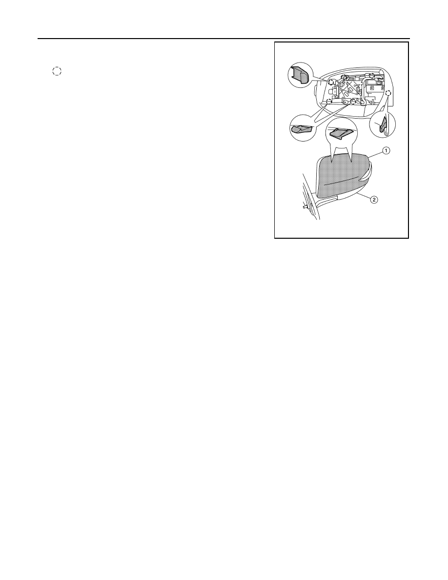
REMOVAL
NOTE:
With side turn signal lamp shown, without is similar.
1. Remove door glass mirror. Refer to
MIR-18, "GLASS MIRROR : Removal and Installation"
.
JMLIA3162ZZ
ALLIA1200ZZ
MIR-20
< REMOVAL AND INSTALLATION >
DOOR MIRROR
2. Using a suitable tool, disengage door mirror cover pawls to sep-
arate the door mirror cover (1) from the door mirror assembly
(2).
: Pawl
INSTALLATION
Installation is in the reverse order of removal.
CAUTION:
After installation, visually check that pawls are securely engaged.
ALLIA1201ZZ
DOOR MIRROR REMOTE CONTROL SWITCH
MIR-21
< REMOVAL AND INSTALLATION >
C
D
E
F
G
H
I
J
K
M
A
B
MIR
N
O
P
DOOR MIRROR REMOTE CONTROL SWITCH
Removal and Installation
INFOID:0000000009757800
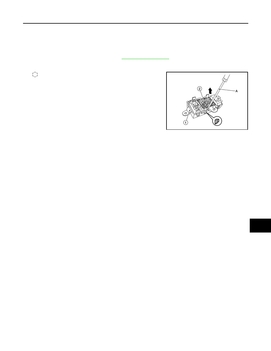
REMOVAL
1. Remove the instrument finisher D. Refer to
2. Using suitable tool (A) release the pawls and remove the door mirror remote control switch (2) from the
switch bracket (1).
: Pawl
INSTALLATION
Installation is in the reverse order of removal.
ALLIA1202ZZ
MWI
MWI-1
DRIVER INFORMATION & MULTIMEDIA
C
D
E
F
G
H
I
J
K
L
M
B
SECTION
MWI
A
O
P
CONTENTS
METER, WARNING LAMP & INDICATOR
PRECAUTION . . . . . . . . . . . ...
PRECAUTIONS . . . . . . . . . . . . ...
SYSTEM DESCRIPTION . . . . . . . ..
COMPONENT PARTS . . . . . . . . . .
METER SYSTEM . . . . . . . . . . . . . .....
METER SYSTEM : Component Parts Location . ....
METER SYSTEM : Component Description . . .....
SYSTEM . . . . . . . . . . . . . . . ..
METER SYSTEM . . . . . . . . . . . . . .....
METER SYSTEM : System Diagram . . . . . ....
METER SYSTEM : System Description . . . . ....
METER SYSTEM : Arrangement of Combination
Meter . . . . . . . . . . . . . . . . . .....
METER SYSTEM : Fail-Safe . . . . . . . . ....
SPEEDOMETER . . . . . . . . . . . . . .
SPEEDOMETER : System Diagram . . . . . ...
SPEEDOMETER : System Description . . . . ...
TACHOMETER . . . . . . . . . . . . . . ..
TACHOMETER : System Diagram . . . . . . .
TACHOMETER : System Description . . . . . .
ENGINE COOLANT TEMPERATURE GAUGE . .
ENGINE COOLANT TEMPERATURE GAUGE :
System Diagram . . . . . . . . . . . . . ..
ENGINE COOLANT TEMPERATURE GAUGE :
System Description . . . . . . . . . . . . .
FUEL GAUGE . . . . . . . . . . . . . . .
FUEL GAUGE : System Diagram . . . . . . ...
FUEL GAUGE : System Description . . . . . ...
OIL PRESSURE WARNING LAMP . . . . . . ...
OIL PRESSURE WARNING LAMP : System Dia-
gram . . . . . . . . . . . . . . . . . .
OIL PRESSURE WARNING LAMP : System De-
scription . . . . . . . . . . . . . . . . ...
METER ILLUMINATION CONTROL . . . . . . .
METER ILLUMINATION CONTROL : System Di-
agram . . . . . . . . . . . . . . . . . ..
METER ILLUMINATION CONTROL : System De-
scription . . . . . . . . . . . . . . . . ...
INFORMATION DISPLAY . . . . . . . . . . ..
INFORMATION DISPLAY : System Diagram . . ..
INFORMATION DISPLAY : System Description . .
COMPASS . . . . . . . . . . . . . . . . .
COMPASS : System Description . . . . . . . .
DIAGNOSIS SYSTEM (COMBINATION
METER) . . . . . . . . . . . . . . . .
Description . . . . . . . . . . . . . . . ...
CONSULT Function (METER/M&A) . . . . . .
ECU DIAGNOSIS INFORMATION . . . ..
COMBINATION METER . . . . . . . . ...
Reference Value . . . . . . . . . . . . . ..
Fail-Safe . . . . . . . . . . . . . . . . ..
DTC Index . . . . . . . . . . . . . . . ...
BCM (BODY CONTROL MODULE) . . . . .
List of ECU Reference . . . . . . . . . . . .
WIRING DIAGRAM . . . . . . . . . ..
METER SYSTEM . . . . . . . . . . . ..
Wiring Diagram . . . . . . . . . . . . . .
COMPASS . . . . . . . . . . . . . . .
Wiring Diagram . . . . . . . . . . . . . .
Нет комментариевНе стесняйтесь поделиться с нами вашим ценным мнением.
Текст