Nissan Qashqai (2007-2010). Manual — part 1960

AV-98
< COMPONENT DIAGNOSIS >
[AUDIO WITH NAVIGATION]
U1250 CAMERA CONTROL UNIT
U1250 CAMERA CONTROL UNIT
Description
INFOID:0000000000947077
DTC Logic
INFOID:0000000000947078
Diagnosis Procedure
INFOID:0000000000947079
1.
CHECK CAMERA-CONNECTION RECOGNITION SIGNAL CIRCUIT
1.
Disconnect NAVI control unit connector and camera control unit connector.
2.
Check continuity between NAVI control unit harness connector terminal 67 and camera control unit har-
ness connector terminal 5.
Is inspection result OK?
YES
>> GO TO 2.
NO
>> Repair harness or connector.
2.
CHECK NAVI CONTROL UNIT VOLTAGE
1.
Connect NAVI control unit connector.
2.
Turn ignition switch ON.
3.
Check voltage between NAVI control unit harness connector terminal 67 and ground.
Is inspection result OK?
YES
>> Replace camera control unit.
NO
>> Replace NAVI control unit.
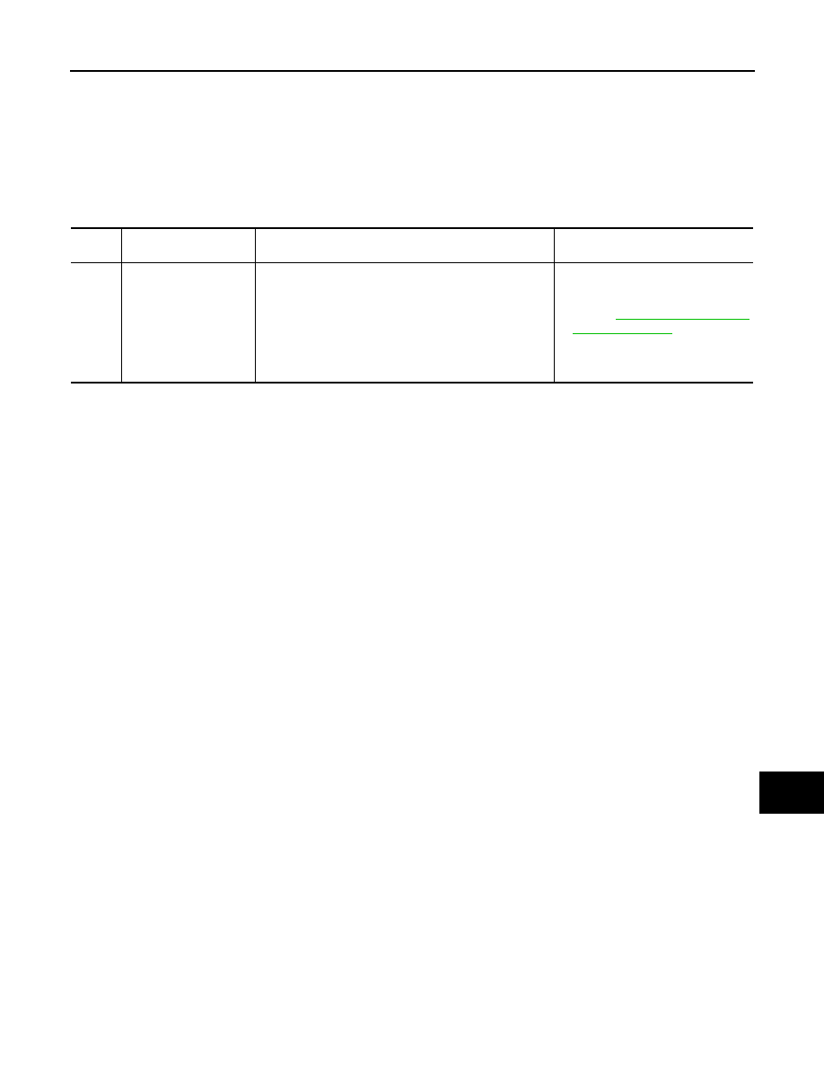
Part name
Description
CAMERA CONTROL UNIT
• Camera image signal is input from rear view camera, and camera image is in-
dicated on the display.
• Power (camera ON signal) is sent to rear view camera.
• It is controlled by AV communication sent from NAVI control unit.
• NAVI control unit recognizes the presence of camera system with camera con-
nection recognition signal.
DTC
Display contents of
CONSULT-III
DTC Detection Condition
Possible causes
U1250
CAMERA CONT. CONN
[U1250]
A malfunction is detected in camera-connection recogni-
tion signal circuit.
Camera-connection recognition sig-
nal circuit
67 - 5
: Continuity should exist.
67 - Ground
: Approx. 5 V
AV
U1300 AV COMM CIRCUIT
AV-99
< COMPONENT DIAGNOSIS >
[AUDIO WITH NAVIGATION]
C
D
E
F
G
H
I
J
K
L
M
B
A
O
P
U1300 AV COMM CIRCUIT
Description
INFOID:0000000000955002
U1300 is indicated when malfunction occurs in communication signal of multi AV system. It is indicated simul-
taneously, without fail, with the malfunction of control units connected to NAVI control unit with communication
line. It determines the possible malfunction cause from the table below.
SELF-DIAGNOSIS RESULTS DISPLAY ITEM
DTC
Display contents of
CONSULT-III
Description
Possible malfunction factor/Action to
take
U1300
U1240
U1249
U124E
U124F
• AV COMM CIRCUIT
[U1300]
• SWITCH CONN
[U1240]
• AUDIO H/U CONN
[U1249]
• AMP CONN [U124E]
• RDS CONN [U124F]
• Audio unit power supply and ground circuit malfunction
is detected.
• Malfunction occurs in AV communication circuit be-
tween NAVI control unit and audio unit.
• Malfunction is detected in AV communication signal be-
tween NAVI control unit and audio unit.
• Audio unit power supply and
ground circuits
Refer to
• AV communication circuit between
NAVI control unit and audio unit
AV-100
< COMPONENT DIAGNOSIS >
[AUDIO WITH NAVIGATION]
POWER SUPPLY AND GROUND CIRCUIT
POWER SUPPLY AND GROUND CIRCUIT
NAVI CONTROL UNIT
NAVI CONTROL UNIT : Diagnosis Procedure
INFOID:0000000000947084
1.
CHECK FUSE
Check for blown fuses.
Is inspection result OK?
YES
>> GO TO 2.
NO
>> Be sure to eliminate cause of malfunction before installing new fuse.
2.
CHECK POWER SUPPLY CIRCUIT
Check voltage between NAVI control unit harness connectors and ground.
Is inspection result OK?
YES
>> GO TO 3.
NO
>> Check harness between NAVI control unit and fuse.
3.
CHECK GROUND CIRCUIT
1.
Turn ignition switch OFF.
2.
Disconnect NAVI control unit connectors.
3.
Check continuity between NAVI control unit harness connector and ground.
Is inspection result OK?
YES
>> INSPECTION END
NO
>> Repair harness or connector.
AUDIO UNIT
AUDIO UNIT : Diagnosis Procedure
INFOID:0000000000954530
1.
CHECK FUSE
Check for blown fuses.
Is inspection result OK?
YES
>> GO TO 2.
NO
>> Be sure to eliminate cause of malfunction before installing new fuse.
2.
CHECK POWER SUPPLY CIRCUIT
Check voltage between audio unit harness connectors and ground.
Power source
Fuse No.
Battery
38
Ignition switch ACC or ON
5
Ignition switch ON or START
4
Signal name
Connector No.
Terminal No.
Ignition switch position
Value (Approx.)
Battery power supply
B95
2
OFF
12 V
ACC power supply
B95
5
ACC
12 V
Ignition signal
B96
63
ON
12 V
Signal name
Connector No.
Terminal No.
Ignition switch position
Continuity
Ground
B95
1
OFF
Continuity should exist.
Power source
Fuse No.
Battery
38
Ignition switch ACC or ON
5
AV
POWER SUPPLY AND GROUND CIRCUIT
AV-101
< COMPONENT DIAGNOSIS >
[AUDIO WITH NAVIGATION]
C
D
E
F
G
H
I
J
K
L
M
B
A
O
P
Is inspection result OK?
YES
>> GO TO 3.
NO
>> Check harness between audio unit and fuse.
3.
CHECK GROUND CIRCUIT
1.
Turn ignition switch OFF.
2.
Disconnect audio unit connectors.
3.
Check continuity between audio unit harness connector and ground.
Is inspection result OK?
YES
>> INSPECTION END
NO
>> Repair harness or connector.
DISPLAY UNIT
DISPLAY UNIT : Diagnosis Procedure
INFOID:0000000000947085
1.
CHECK FUSE
Check for blown fuses.
Is inspection result OK?
YES
>> GO TO 2.
NO
>> Be sure to eliminate cause of malfunction before installing new fuse.
2.
CHECK POWER SUPPLY CIRCUIT
Check voltage between display unit harness connectors and ground.
Is inspection result OK?
YES
>> GO TO 3.
NO
>> Check harness between display unit and fuse.
3.
CHECK GROUND CIRCUIT
1.
Turn ignition switch OFF.
2.
Disconnect display unit connector.
3.
Check continuity between display unit harness connector and ground.
Is inspection result OK?
YES
>> INSPECTION END
NO
>> Repair harness or connector.
CAMERA CONTROL UNIT
Signal name
Connector No.
Terminal No.
Ignition switch position
Value (Approx.)
Battery power supply
M46
19
OFF
12 V
ACC power supply
M46
7
ACC
12 V
Signal name
Connector No.
Terminal No.
Ignition switch position
Continuity
Ground
M46
8, 20
OFF
Continuity should exist.
Power source
Fuse No.
Battery
38
Ignition switch ACC or ON
5
Signal name
Connector No.
Terminal No.
Ignition switch position
Value (Approx.)
Battery power supply
M49
21
OFF
12 V
ACC power supply
M49
20
ACC
12 V
Signal name
Connector No.
Terminal No.
Ignition switch position
Continuity
Ground
M49
23
OFF
Continuity should exist.
Нет комментариевНе стесняйтесь поделиться с нами вашим ценным мнением.
Текст