Nissan Qashqai (2007-2010). Manual — part 1959
AV-94
< COMPONENT DIAGNOSIS >
[AUDIO WITH NAVIGATION]
U1215 NAVI CONTROL UNIT
U1215 NAVI CONTROL UNIT
Description
INFOID:0000000000954957
DTC Logic
INFOID:0000000000954958
Diagnosis Procedure
INFOID:0000000000954959
1.
PERFORM THE SELF-DIAGNOSIS
1.
Delete the self-diagnosis results. Turn ignition switch OFF.
2.
Turn ignition switch ON. Replace map DVD-ROM with a normal one.
3.
Perform the self-diagnosis again.
4.
Check that the DTC is detected again.
Is any DTC detected?
YES
>> Replace NAVI control unit.
NO
>> Replace Map disc.
Part name
Description
NAVI CONTORL UNIT
• Map data can be read from the map DVD-ROM by installing map DVD-ROM.
• It is the master unit of the MULTI AV system, and it is connected to each control
unit by means of communication. It operates each system according to com-
munication signals from the NAVI control unit.
• The NAVI control unit includes the audio, hands-free phone, navigation, and
vehicle information functions.
• It is connected to ECM and combination meter via CAN communication to ob-
tain necessary information for the vehicle information function.
• It inputs the illumination signals that are required for the display dimming con-
trol.
• It inputs the signals for driving status recognition (vehicle speed, reverse and
parking brake).
MAP DVD-ROM
A collection of map data
DTC
Display contents of
CONSULT-III
DTC Detection Condition
Probable malfunction location
U1215
DVD-ROM LOAD
[U1215]
• Malfunction is detected on DVD-ROM drive pickup lens
in NAVI control unit.
• There is dirt and damage on the map disc.
• Map disc
• NAVI control unit

AV
U1243 DISPLAY UNIT
AV-95
< COMPONENT DIAGNOSIS >
[AUDIO WITH NAVIGATION]
C
D
E
F
G
H
I
J
K
L
M
B
A
O
P
U1243 DISPLAY UNIT
Description
INFOID:0000000000947068
DTC Logic
INFOID:0000000000947069
Diagnosis Procedure
INFOID:0000000000947070
1.
CHECK DISPLAY UNIT POWER SUPPLY AND GROUND CIRCUIT
Check display unit power supply and ground circuit. Refer to
AV-101, "DISPLAY UNIT : Diagnosis Procedure"
.
Is inspection result OK?
YES
>> GO TO 2.
NO
>> Repair malfunctioning parts.
2.
CHECK CONTINUITY COMMUNICATION CIRCUIT
1.
Turn ignition switch OFF.
2.
Disconnect display unit connector and NAVI control unit connector.
3.
Check continuity between display unit harness connector terminals 17, 19 and NAVI control unit harness
connector terminals 54, 53.
4.
Check continuity between display unit harness connector terminals 17, 19 and ground.
Is inspection result OK?
YES
>> GO TO 3.
NO
>> Repair harness or connector.
3.
CHECK COMMUNICATION SIGNAL
1.
Connect display unit connector and NAVI control unit connector.
2.
Turn ignition switch ON.
3.
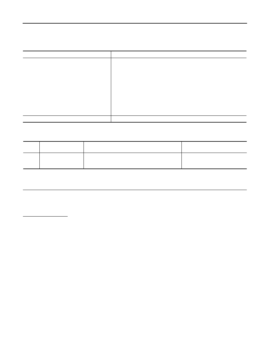
Check signal between display unit harness connector terminal 17 and ground.
Part name
Description
DISPLAY UNIT
• Display image is controlled by the serial communication from NAVI control unit.
• RGB image signal is input from NAVI control unit (RGB, RGB area and RGB
synchronizing). Camera image signal is input from camera control unit.
• Synchronize signal (HP, VP) is output to NAVI control unit.
DTC
Display contents of
CONSULT-III
DTC Detection Condition
Possible causes
U1243
FRONT DISP CONN
[U1243]
• Display unit power supply and ground circuit malfunc-
tion is detected.
• Malfunction is detected on communication circuit be-
tween display unit and NAVI control unit.
• Malfunction is detected on communication signal be-
tween display unit and NAVI control unit.
• Display unit power supply and
ground circuit
• Communication circuit between
display unit and NAVI control unit
17 - 54
: Continuity should exist.
19 - 53
: Continuity should exist.
17, 19 - Ground
: Continuity should not exist.
AV-96
< COMPONENT DIAGNOSIS >
[AUDIO WITH NAVIGATION]
U1243 DISPLAY UNIT
Is inspection result OK?
YES
>> GO TO 4.
NO
>> Replace NAVI control unit.
4.
CHECK COMMUNICATION SIGNAL
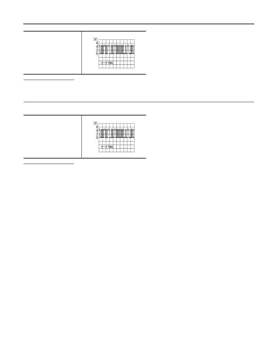
Check signal between display unit harness connector terminal 19 and ground.
Is inspection result OK?
YES
>> INSPECTION END
NO
>> Replace display unit.
17 - Ground
PKIB5039J
19 - Ground
PKIB5039J

AV
U1244 GPS ANTENNA
AV-97
< COMPONENT DIAGNOSIS >
[AUDIO WITH NAVIGATION]
C
D
E
F
G
H
I
J
K
L
M
B
A
O
P
U1244 GPS ANTENNA
Description
INFOID:0000000000947071
DTC Logic
INFOID:0000000000947072
Diagnosis Procedure
INFOID:0000000000947073
1.
CHECK GPS ANTENNA
Visually check GPS antenna and antenna feeder.
Is inspection result OK?
YES
>> GO TO 2.
NO
>> Repair malfunctioning parts.
2.
CHECK NAVI CONTROL UNIT VOLTAGE
1.
Disconnect GPS antenna connector.
2.
Turn ignition switch ON.
3.
Check voltage between NAVI control unit terminal 73 and ground.
Is inspection result OK?
YES
>> INSPECTION END
NO
>> Replace NAVI control unit.
Part name
Description
GPS ANTENNA
GPS signal is received and sent to NAVI control unit.
DTC
Display contents of
CONSULT-III
DTC Detection Condition
Possible causes
U1244
GPS ANTENNA CONN
[U1244]
GPS antenna connection malfunction is detected.
GPS antenna disconnection
73 - Ground
: Approx. 5 V
Нет комментариевНе стесняйтесь поделиться с нами вашим ценным мнением.
Текст