Nissan Qashqai (2007-2010). Manual — part 1480
BCS-10
< FUNCTION DIAGNOSIS >
COMBINATION SWITCH READING SYSTEM
NOTE:
Headlamp has a dual system switch.
COMBINATION SWITCH READING FUNCTION
Description
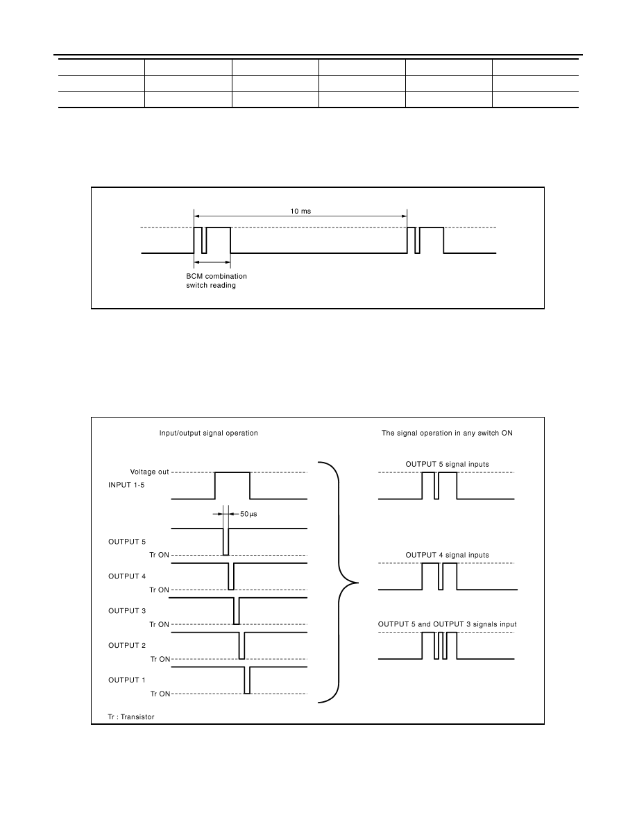
• BCM reads the status of the combination switch at 10 ms interval normally.
NOTE:
BCM reads the status of the combination switch at 20 ms interval when BCM is controlled at low power con-
sumption control mode.
• BCM operates as follows and judges the status of the combination switch.
- INPUT 1 - 5 outputs the voltage waveforms of 5 systems simultaneously.
- It operates the transistor on OUTPUT side in the following order: OUTPUT 5
→
4
→
3
→
2
→
1.
- The voltage waveform of INPUT corresponding to the formed circuit changes according to the operation of
the transistor on OUTPUT side if any (1 or more) switches are ON.
- It reads this change of the voltage as the status signal of the combination switch.
Operation Example
In the following operation example, the combination of the status signals of the combination switch is replaced
as follows: INPUT 1 - 5 to “1 - 5” and OUTPUT 1 - 5 to “A - E”.
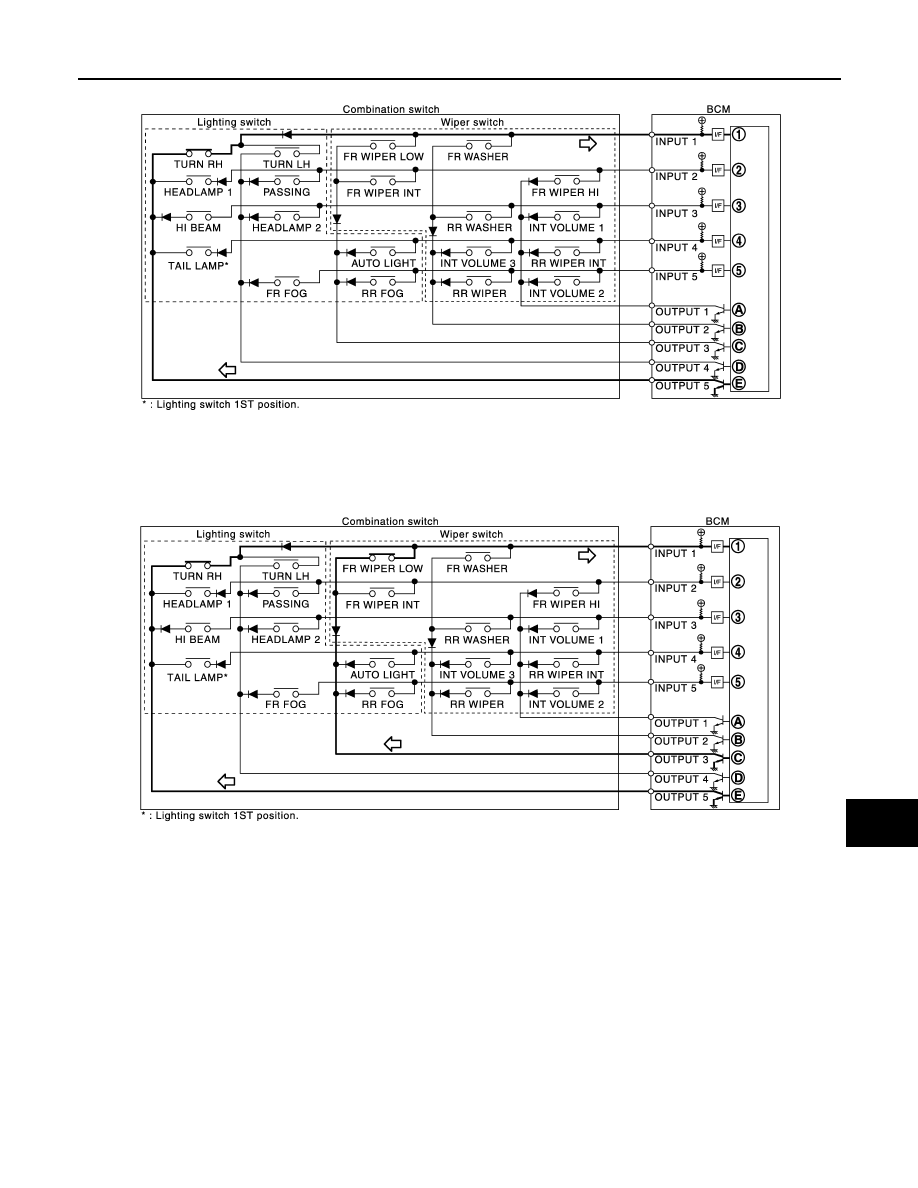
Example 1: When a switch (TURN RH switch) is turned ON
INPUT 4
RR WIPER INT
INT VOLUME 3
AUTO LIGHT
—
TAIL LAMP
INPUT 5
INT VOLUME 2
RR WIPER
RR FOG
FR FOG
—
System
OUTPUT 1
OUTPUT 2
OUTPUT 3
OUTPUT 4
OUTPUT 5
JPMIA0067GB
JPMIA0068GB
BCS
COMBINATION SWITCH READING SYSTEM
BCS-11
< FUNCTION DIAGNOSIS >
C
D
E
F
G
H
I
J
K
L
B
A
O
P
N
• The circuit between INPUT 1 and OUTPUT 5 is formed when the TURN RH switch is turned ON.
• BCM detects the combination switch status signal “1E” when the signal of OUTPUT 5 is input to INPUT 1.
• BCM judges that the TURN RH switch is ON when the signal “1E” is detected.
Example 2: When some switches (turn RH switch, front wiper LO switch) are turned ON
• The circuits between INPUT 1 and OUTPUT 5 and between INPUT 1 and OUTPUT 3 are formed when the
TURN RH switch and FR WIPER LOW switch are turned ON.
• BCM detects the combination switch status signal “1CE” when the signals of OUTPUT 3 and OUTPUT 5 are
input to INPUT 1.
• BCM judges that the TURN RH switch and FR WIPER LOW switch are ON when the signal “1CE” is
detected.
WIPER INTERMITTENT DIAL POSITION SETTING (FRONT WIPER INTERMITTENT OPERATION)
BCM judges the wiper intermittent dial 1 - 7 by the status of INT VOLUME 1, 2 and 3 switches.
JPMIA0122GB
JPMIA0123GB
BCS-12
< FUNCTION DIAGNOSIS >
COMBINATION SWITCH READING SYSTEM
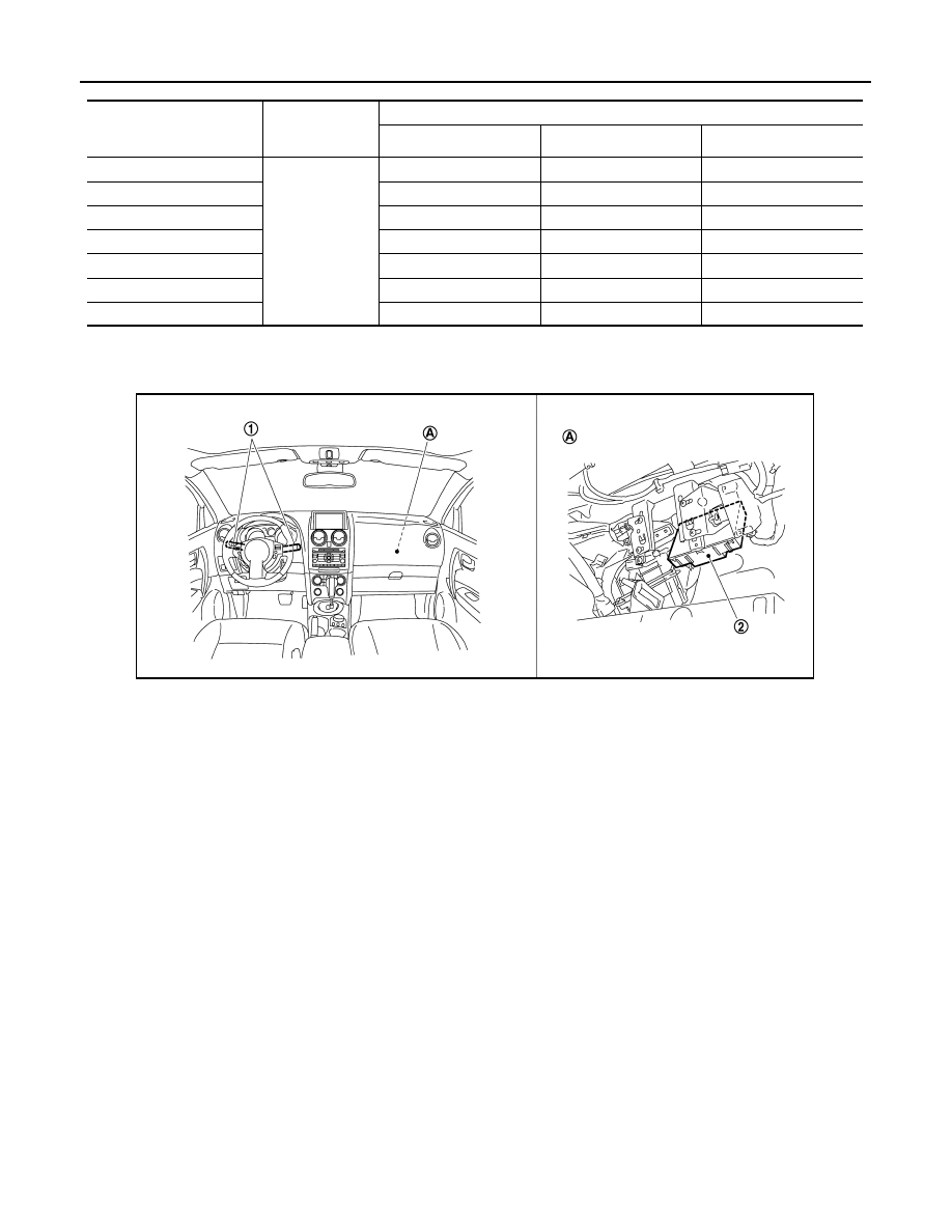
Component Parts Location
INFOID:0000000000924595
Wiper intermittent
dial position
Intermittent
operation delay
interval
INT VOLUME switch ON/OFF status
INT VOLUME 1 switch
INT VOLUME 2 switch
INT VOLUME 3 switch
1
Short
↑
↓
Long
ON
ON
ON
2
ON
ON
OFF
3
ON
OFF
OFF
4
OFF
OFF
OFF
5
OFF
OFF
ON
6
OFF
ON
ON
7
OFF
ON
OFF
1.
Combination switch
2.
BCM
A.
Over the glove box
JPMIA0243ZZ
BCS
SIGNAL BUFFER SYSTEM
BCS-13
< FUNCTION DIAGNOSIS >
C
D
E
F
G
H
I
J
K
L
B
A
O
P
N
SIGNAL BUFFER SYSTEM
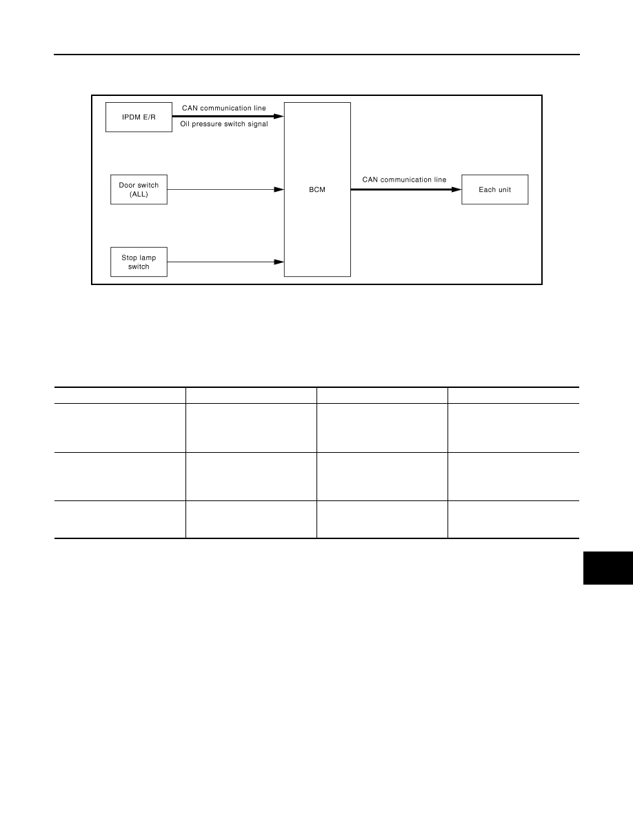
System Diagram
INFOID:0000000000924596
System Description
INFOID:0000000000924597
OUTLINE
BCM has the signal transmission function that outputs/transmits each input/received signal to each unit.
Signal transmission function list
JPMIA0124GB
Signal name
Input
Output
Description
Door switch signal
Any door switch
• Combination meter (CAN)
• IPDM E/R (CAN)
• Intelligent Key unit (CAN)
• NAVI control unit (CAN)
Inputs the door switch signal
and transmits it via CAN com-
munication.
Stop lamp switch signal
Stop lamp switch
TCM (CAN)
Inputs the stop lamp switch sig-
nal and transmits the stop lamp
switch signal via CAN commu-
nication.
Oil pressure switch signal
IPDM E/R (CAN)
Combination meter (CAN)
Transmits the received oil pres-
sure switch signal via CAN
communication.
Нет комментариевНе стесняйтесь поделиться с нами вашим ценным мнением.
Текст