Nissan Qashqai (2007-2010). Manual — part 1481
BCS-14
< FUNCTION DIAGNOSIS >
POWER CONSUMPTION CONTROL SYSTEM
POWER CONSUMPTION CONTROL SYSTEM
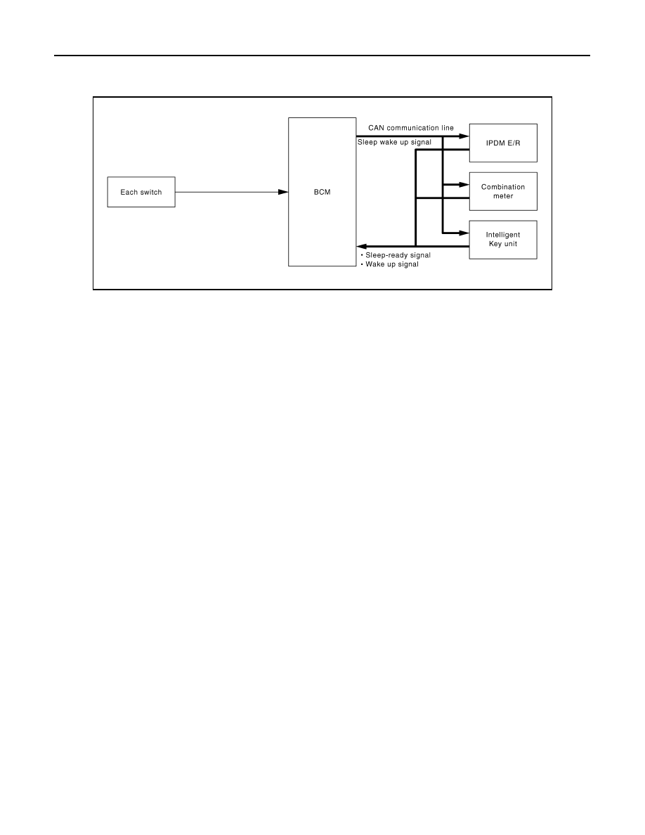
System Diagram
INFOID:0000000000924598
System Description
INFOID:0000000000924599
OUTLINE
• BCM incorporates a power consumption control function that reduces the power consumption according to
the vehicle status.
• BCM switches the status (control mode) by itself with the power saving control function. It performs the sleep
request to each unit (IPDM E/R, combination meter and Intelligent Key unit) that operates with the ignition
switch OFF.
Normal mode (wake-up)
- CAN communication is normally performed with other units
- Each control with BCM is operating properly
CAN communication sleep mode (CAN sleep)
- CAN transmission is stopped
- Control with BCM only is operating
Low power consumption mode (BCM sleep)
- Low power consumption control is active
- CAN transmission is stopped
LOW POWER CONSUMPTION CONTROL WITH BCM
BCM reduces the power consumption with the following operation in the low power consumption mode.
• The reading interval of the each switches changes from 10 ms interval to 20 ms interval.
Sleep mode activation
• BCM receives the sleep-ready signal (ready) from IPDM E/R, combination meter and Intelligent Key unit via
CAN communication.
• BCM transmits the sleep wake up signal (sleep) to each unit when all of the CAN sleep conditions are ful-
filled.
• Each unit stops the transmission of CAN communication with the sleep wake up signal. BCM is in CAN com-
munication sleep mode.
• BCM is in the low power consumption mode and perform the low power consumption control when all of the
BCM sleep conditions are fulfilled with CAN sleep condition.
JPMIA0125GB

BCS
POWER CONSUMPTION CONTROL SYSTEM
BCS-15
< FUNCTION DIAGNOSIS >
C
D
E
F
G
H
I
J
K
L
B
A
O
P
N
Sleep condition
Wake-up operation
• BCM transmits sleep wake up signal (wake up) to each unit when any condition listed below is established,
and then goes into normal mode from low power consumption mode.
• Each unit starts transmissions with CAN communication by receiving sleep wake up signals. Each unit trans-
mits wake up signals to BCM with CAN communication to convey the start of CAN communication.
Wake-up condition
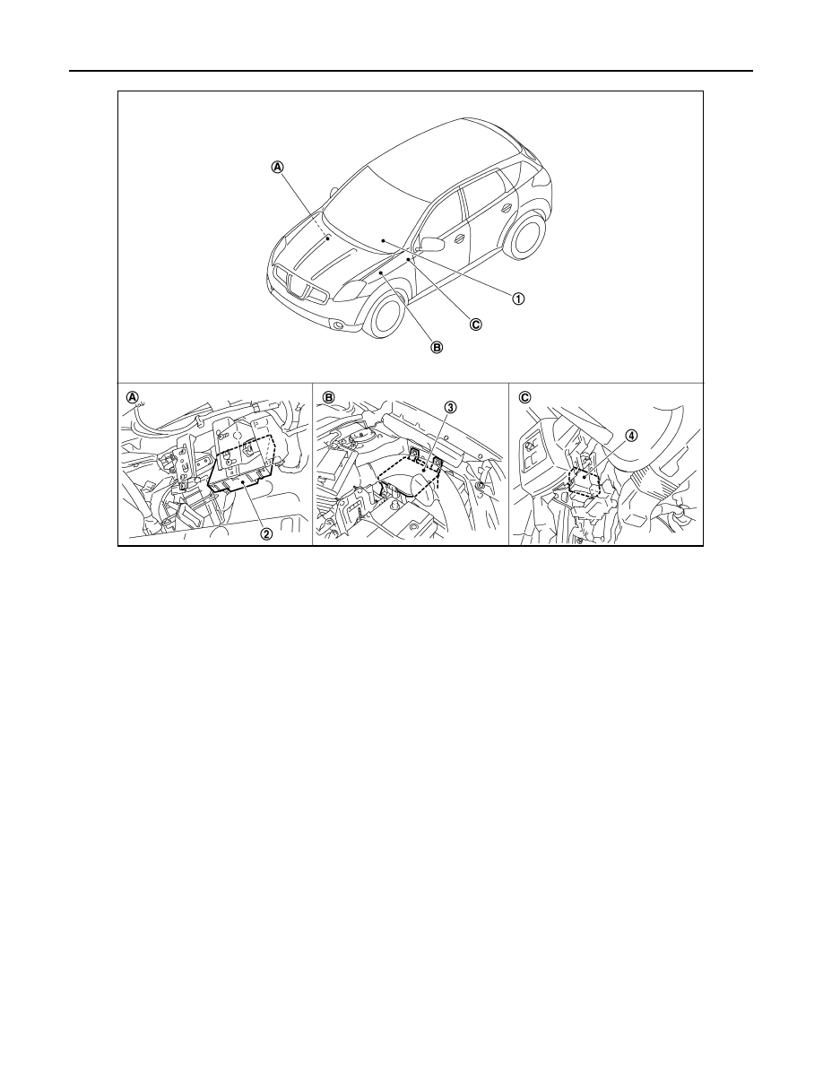
Component Parts Location
INFOID:0000000000924600
CAN sleep condition
BCM sleep condition
• Receiving the sleep-ready signal (ready) from all units
• Ignition switch: OFF
• Vehicle security system alarm: Not operation
• Warning lamp: Not operation
• Warning chime: Not operation
• Stop lamp switch: OFF
• Key switch status: No change for 2seconds
• Hazard warning lamp: Not operation
• Exterior lamp: OFF
• Door lock status: No change for 2seconds
• CONSULT-III communication status: Not communication
• Door switch status: No change for 2seconds
The controls only BCM are completed.
(Interior room lamp battery saver: Time out etc.)
BCM wake-up condition
• Ignition switch: OFF
→
ACC or ON
• Stop lamp switch: ON (Depress brake pedal)
• Any door switch: OFF
→
ON
• Lighting switch: OFF
→
1ST or PASS
• Hazard switch: OFF
→
ON
• Back door opener switch OFF
→
ON
• Remote keyless entry receiver: Receiving
BCS-16
< FUNCTION DIAGNOSIS >
POWER CONSUMPTION CONTROL SYSTEM
1.
Combination meter
2.
BCM
3.
IPDM E/R
4.
Intelligent Key unit
A.
Over the glove box
B.
Engine room (left side)
C.
Over the instrument lower panel
(driver side)
JPMIA0239ZZ

BCS
DIAGNOSIS SYSTEM (BCM)
BCS-17
< FUNCTION DIAGNOSIS >
C
D
E
F
G
H
I
J
K
L
B
A
O
P
N
DIAGNOSIS SYSTEM (BCM)
COMMON ITEM
COMMON ITEM : CONSULT-III Function (BCM - COMMON ITEM)
INFOID:0000000000924601
APPLICATION ITEM
CONSULT-III performs the following functions via CAN communication with BCM.
SYSTEM APPLICATION
BCM can perform the following functions for each system.
NOTE:
It can perform the diagnosis modes except the following for all sub system selection items.
BCM
BCM : CONSULT-III Function (BCM - BCM)
INFOID:0000000000924608
WORK SUPPORT
Diagnosis mode
Function Description
WORK SUPPORT
Changes the setting for each system function.
SELF-DIAG RESULTS
Displays the diagnosis results judged by BCM. Refer to
CAN DIAG SUPPORT MNTR
Monitors the reception status of CAN communication viewed from BCM.
DATA MONITOR
The BCM input/output signals are displayed.
ACTIVE TEST
The signals used to activate each device are forcibly supplied from BCM.
ECU IDENTIFICATION
The BCM part number is displayed.
CONFIGURATION
• Enables to read and save the vehicle specification.
• Enables to write the vehicle specification when replacing BCM.
System
Sub system selection item
Diagnosis mode
WORK SUPPORT
DATA MONITOR
ACTIVE TEST
—
BCM
×
Door lock
DOOR LOCK
×
×
×
Rear window defogger
REAR DEFOGGER
×
×
Warning chime
BUZZER
×
×
Interior room lamp timer
INT LAMP
×
×
×
Remote keyless entry system
MULTI REMOTE ENT
×
×
×
Exterior lamp
HEAD LAMP
×
×
×
Wiper and washer
WIPER
×
×
×
Turn signal and hazard warning lamps
FLASHER
×
×
Air conditioner
AIR CONDITONER
×
Intelligent Key system
INTELLIGENT KEY
×
Combination switch
COMB SW
×
Immobilizer
IMMU
×
×
Interior room lamp battery saver
BATTERY SAVER
×
×
×
Trunk open
TRUNK
×
Vehicle security system
THEFT ALM
×
×
×
Signal buffer system
SIGNAL BUFFER
×
×
PTC heater system
PTC HEATER
×
×
Нет комментариевНе стесняйтесь поделиться с нами вашим ценным мнением.
Текст