Nissan Qashqai (2007-2010). Manual — part 664
REAR DRIVE SHAFT
RAX-13
< ON-VEHICLE REPAIR >
[4WD]
C
E
F
G
H
I
J
K
L
M
A
B
RAX
N
O
P
REAR DRIVE SHAFT
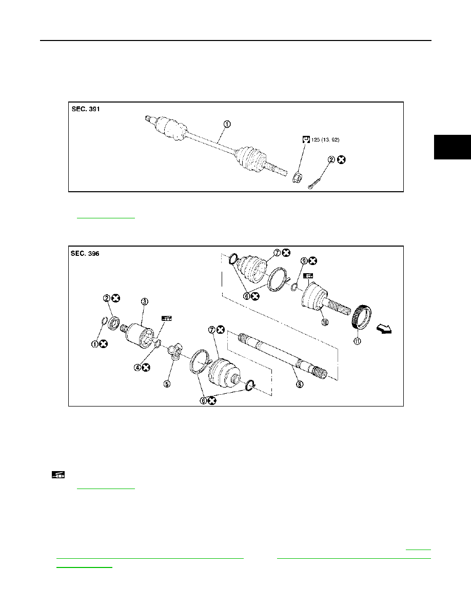
Exploded View
INFOID:0000000000970510
REMOVAL
DISASSEMBLY
Removal and Installation
INFOID:0000000000970511
REMOVAL
1.
Remove tires from vehicle.
2.
Remove torque member mounting bolts. Hang torque member not to interfere with work. Refer to
"BRAKE CALIPER ASSEMBLY : Exploded View"
(LHD),
BR-86, "BRAKE CALIPER ASSEMBLY :
(RHD).
CAUTION:
Never depress brake pedal while brake caliper is removed.
1.
Drive shaft
2.
Cotter pin
Refer to
PDIA1172J
1.
Circular clip
2.
Dust shield
3.
Housing
4.
Snap ring
5.
Spider assembly
6.
Boot band
7.
Boot
8.
Shaft
9.
Circular clip
10. Joint sub-assembly
11.
Sensor rotor
: Wheel side
: Fill NISSAN genuine grease or an equivalent.
Refer to
for symbols not described on the above.
JPDIG0015ZZ
RAX-14
< ON-VEHICLE REPAIR >
[4WD]
REAR DRIVE SHAFT
3.
Remove disc rotor. Refer to
PB-7, "Removal and Installation"
4.
Remove cotter pin, then loosen hub lock nut.
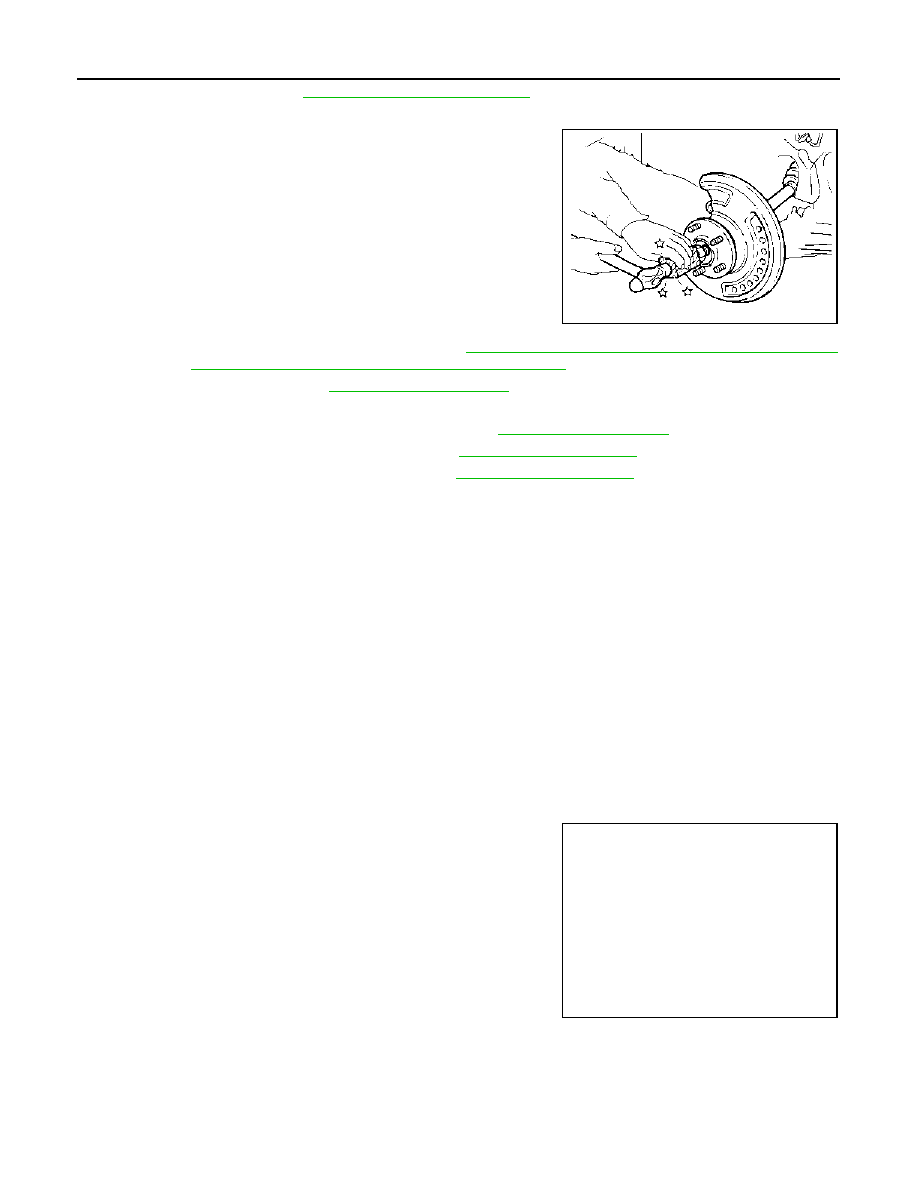
5.
Patch hub lock nut with a piece of wood. Hammer the wood to
disengage wheel hub and bearing assembly from drive shaft.
Remove the hub lock nut.
CAUTION:
• Never place drive shaft joint at an extreme angle. Also be
careful not to overextend slide joint.
• Never allow drive shaft to hang down without support for
housing (or joint sub-assembly), shaft and the other parts.
NOTE:
Using a suitable puller if the wheel hub and bearing assembly
and drive shaft cannot be separated even after performing the
above procedure.
6.
Remove wheel sensor from axle housing. Refer to
BRC-67, "REAR WHEEL SENSOR : Exploded View"
(with ABS),
BRC-172, "REAR WHEEL SENSOR : Exploded View"
(with ESP).
7.
Remove stabilizer link. Refer to
8.
Set suitable jack under suspension arm.
9.
Remove shock absorber from suspension arm. Refer to
10. Remove upper link from suspension arm. Refer to
11. Remove lower link from suspension arm. Refer to
.
12. Remove drive shaft from final drive assembly.
INSTALLATION
Note the following, and install in the reverse order of removal.
• Perform final tightening of bolts and nuts at suspension arm (rubber bushing), under unladen conditions with
tires on level ground.
Disassembly and Assembly
INFOID:0000000001082911
DISASSEMBLY
Final Drive Side
1.
Fix shaft with a vise.
CAUTION:
Protect shaft using aluminum or copper plates when fixing with a vise.
2.
Remove boot bands, and then remove boot from housing.
3.
Put matching marks on housing and shaft.
CAUTION:
Use paint or an equivalent for matching marks. Never scratch the surface.
4.
Put matching marks (A) on the spider assembly and shaft.
CAUTION:
Use paint or an equivalent for matching marks. Never
scratch the surface.
JPDIF0003ZZ
JPDIF0006ZZ
REAR DRIVE SHAFT
RAX-15
< ON-VEHICLE REPAIR >
[4WD]
C
E
F
G
H
I
J
K
L
M
A
B
RAX
N
O
P
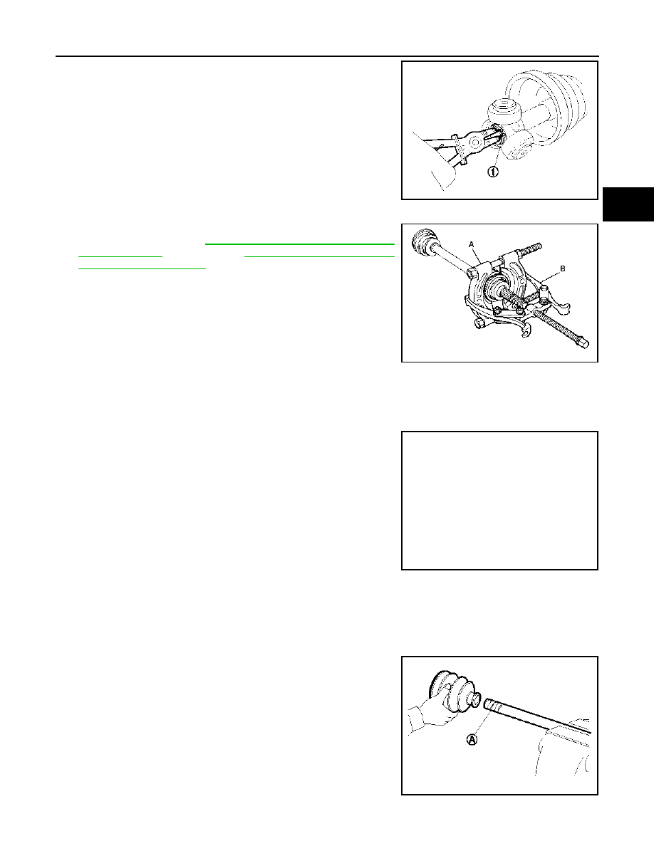
5.
Remove snap ring (1), and then remove spider assembly from
shaft.
6.
Remove boot from shaft.
7.
Remove circular clip housing.
8.
Remove dust shield to housing.
9.
Remove old grease on housing with paper towels.
Wheel Side
1.
If sensor rotor needs to be removed, use a bearing replacer (A)
and puller (B). Refer to
(with ABS),
2.
Fix shaft with a vise.
CAUTION:
Protect shaft using aluminum or copper plates when fixing with a vise.
3.
Remove boot bands. Then remove boot from joint sub-assembly.
4.
Screw the drive shaft puller (A) 30 mm (1.18 in) or more into the
thread of joint sub-assembly, and pull joint sub-assembly with a
sliding hammer (B) from shaft.
CAUTION:
• If joint sub-assembly cannot be removed after five or
more unsuccessful attempts, replace shaft and joint sub
assembly as a set.
• Align sliding hammer and drive shaft and remove them by
pulling directory.
5.
Remove boot from shaft.
6.
Remove circular clip.
CAUTION:
Never reuse circular clip.
7.
While rotating ball cage, clean old grease on joint sub-assembly with paper towels.
ASSEMBLY
Final drive Side
1.
Wrap serrated part of shaft with tape (A). Install boot band and
boot to shaft. Be careful not to damage boot.
CAUTION:
Never reuse boot and boot band.
2.
Remove the tape wrapped around the serrated on shaft.
JPDIF0014ZZ
JPDIG0016ZZ
JPDIF0015ZZ
JPDIF0009ZZ
RAX-16
< ON-VEHICLE REPAIR >
[4WD]
REAR DRIVE SHAFT
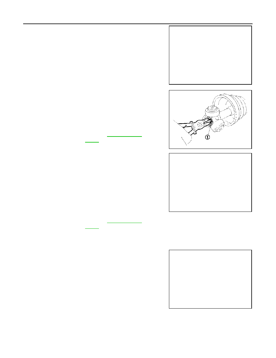
3.
To install the spider assembly (1), align it with the matching
marks (A) that were on the shaft (2) during the removal, and
direct the serration mounting surface (B) to the shaft.
4.
Secure spider assembly onto shaft with snap ring (1).
5.
Apply the appropriate amount of grease onto housing and slid
surface.
6.
Assemble the housing onto spider assembly, and apply the bal-
ance of the specified amount grease.
7.
Align matching marks painted when housing were removed.
8.
Install boot securely into grooves (indicated by “*” marks) shown
in the figure.
CAUTION:
If there is grease on boot mounting surfaces (indicated by
“*” marks) of shaft or housing, boot may be removed.
Remove all grease from the surfaces.
9.
To prevent from deformation of the boot, adjust the boot installa-
tion length to the value shown below (L) by inserting the suitable
tool into the inside of boot from the large diameter side of boot
and discharging inside air.
CAUTION:
• If the boot installation length exceeds the standard, it may cause breakage in boot.
• Be careful not to touch the inside of the boot with the tip of tool.
10. Secure large and small ends of boot with new boot bands as
shown in the figure.
CAUTION:
Never reuse boot band.
11. Secure housing and shaft, and then make sure that they are in
the correct position when rotating boot. Install them with new
boot band when the mounting positions become incorrect.
12. Install dust shield to housing.
CAUTION:
Never reuse dust shield.
13. Install circular clip to housing.
CAUTION:
Never reuse circular clip.
Wheel Side
JPDIF0017ZZ
Standard
Grease amount
: Refer to
.
Standard
Boots installed
length (L)
: Refer to
.
JPDIF0014ZZ
JPDIF0032ZZ
PDIA1188J
Нет комментариевНе стесняйтесь поделиться с нами вашим ценным мнением.
Текст