Nissan Qashqai (2007-2010). Manual — part 1330
REAR FOG LAMP SYSTEM
EXL-25
< FUNCTION DIAGNOSIS >
[XENON TYPE]
C
D
E
F
G
H
I
J
K
M
A
B
EXL
N
O
P
REAR FOG LAMP SYSTEM
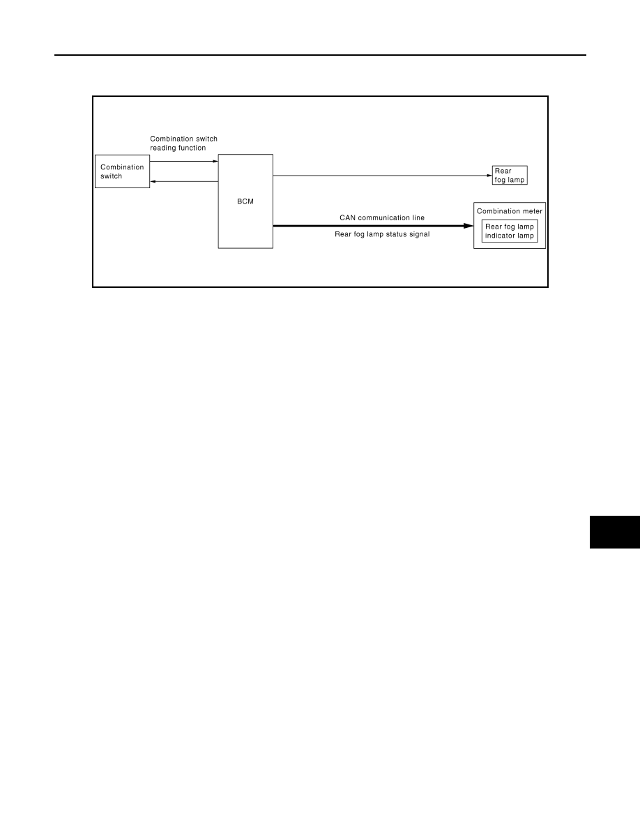
System Diagram
INFOID:0000000000955396
System Description
INFOID:0000000000955397
OUTLINE
Rear fog lamp is controlled with the combination switch reading function and the rear fog lamp control function
of BCM.
REAR FOG LAMP OPERATION
• BCM detects the condition of the combination switch by the combination switch reading function.
• BCM supplies voltage to rear fog lamp according to the rear fog lamp ON condition.
Rear fog lamp ON condition
- Rear fog lamp switch signal is input with front fog lamp ON and rear fog lamp OFF
Rear fog lamp OFF condition
- Rear fog lamp switch signal is input with rear fog lamp ON
- Front fog lamp OFF
• BCM transmits the rear fog lamp status signal to the combination meter with CAN communication.
• Combination meter turns the rear fog lamp indicator lamp ON according to the rear fog lamp status signal.
Component Parts Location
INFOID:0000000000955398
JPLIA0179GB

EXL-26
< FUNCTION DIAGNOSIS >
[XENON TYPE]
REAR FOG LAMP SYSTEM
Component Description
INFOID:0000000000955399
1.
Combination switch
2.
Rear fog lamp
3.
BCM
4.
Rear fog lamp indicator lamp
A.
Over the glove box
B.
On the combination meter
JPLIA0192ZZ
Part
Description
BCM
• Detects each switch condition by the combination switch reading function.
• Judges that the rear fog lamp is turned ON according to the vehicle status
- Supplies voltage to the rear fog lamp
- Requests the rear fog lamp indicator lamp ON to the combination meter (with CAN
communication).
Combination switch
(Lighting & turn signal switch)
Refer to
.
Combination meter
(Rear fog lamp indicator lamp)
Turns the rear fog lamp indicator lamp ON according to the request from BCM (with CAN
communication).
DIAGNOSIS SYSTEM (BCM)
EXL-27
< FUNCTION DIAGNOSIS >
[XENON TYPE]
C
D
E
F
G
H
I
J
K
M
A
B
EXL
N
O
P
DIAGNOSIS SYSTEM (BCM)
COMMON ITEM
COMMON ITEM : CONSULT-III Function (BCM - COMMON ITEM)
INFOID:0000000001116333
APPLICATION ITEM
CONSULT-III performs the following functions via CAN communication with BCM.
SYSTEM APPLICATION
BCM can perform the following functions for each system.
NOTE:
It can perform the diagnosis modes except the following for all sub system selection items.
HEADLAMP
HEADLAMP : CONSULT-III Function (BCM - HEAD LAMP)
INFOID:0000000001026151
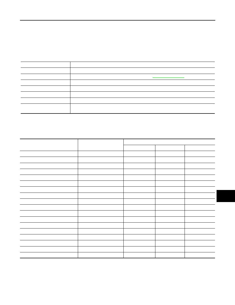
WORK SUPPORT
Diagnosis mode
Function Description
WORK SUPPORT
Changes the setting for each system function.
SELF-DIAG RESULTS
Displays the diagnosis results judged by BCM. Refer to
CAN DIAG SUPPORT MNTR
Monitors the reception status of CAN communication viewed from BCM.
DATA MONITOR
The BCM input/output signals are displayed.
ACTIVE TEST
The signals used to activate each device are forcibly supplied from BCM.
ECU IDENTIFICATION
The BCM part number is displayed.
CONFIGURATION
• Enables to read and save the vehicle specification.
• Enables to write the vehicle specification when replacing BCM.
System
Sub system selection item
Diagnosis mode
WORK SUPPORT
DATA MONITOR
ACTIVE TEST
—
BCM
×
Door lock
DOOR LOCK
×
×
×
Rear window defogger
REAR DEFOGGER
×
×
Warning chime
BUZZER
×
×
Interior room lamp timer
INT LAMP
×
×
×
Remote keyless entry system
MULTI REMOTE ENT
×
×
×
Exterior lamp
HEAD LAMP
×
×
×
Wiper and washer
WIPER
×
×
×
Turn signal and hazard warning lamps
FLASHER
×
×
Air conditioner
AIR CONDITONER
×
Intelligent Key system
INTELLIGENT KEY
×
Combination switch
COMB SW
×
Immobilizer
IMMU
×
×
Interior room lamp battery saver
BATTERY SAVER
×
×
×
Trunk open
TRUNK
×
Vehicle security system
THEFT ALM
×
×
×
Signal buffer system
SIGNAL BUFFER
×
×
PTC heater system
PTC HEATER
×
×

EXL-28
< FUNCTION DIAGNOSIS >
[XENON TYPE]
DIAGNOSIS SYSTEM (BCM)
*: Initial setting
DATA MONITOR
ACTIVE TEST
Service item
Setting item
Setting
HEAD LIGHT TIMER
MODE 1
10 sec.
Sets follow me home function activating time.
MODE 2
*
30 sec.
Monitor item
[Unit]
Description
IGN ON SW
[ON/OFF]
Ignition switch (ON) status judged from IGN signal (ignition power supply)
ACC SW
[ON/OFF]
Ignition switch (ACC) status judged from ACC signal (ACC power supply)
HI BEAM SW
[ON/OFF]
Each switch status that BCM judges from the combination switch reading function
HEAD LAMP SW1
[ON/OFF]
HEAD LAMP SW2
[ON/OFF]
TAIL LAMP SW
[ON/OFF]
AUTO LIGHT SW
[ON/OFF]
PASSING SW
[ON/OFF]
FR FOG SW
[ON/OFF]
RR FOG SW
[ON/OFF]
DOOR SW-DR
[ON/OFF]
The switch status input from front door switch (driver side)
DOOR SW-AS
[ON/OFF]
The switch status input from front door switch (passenger side)
DOOR SW-RR
[ON/OFF]
The switch status input from rear door switch RH
DOOR SW- RL
[ON/OFF]
The switch status input from rear door switch LH
BACK DOOR SW
[ON/OFF]
The switch status input from back door switch
TURN SIGNAL R
[ON/OFF]
Each switch status that BCM judges from the combination switch reading function
TURN SIGNAL L
[ON/OFF]
ENGINE RUNNING
[ON/OFF]
The engine status received from ECM with CAN communication
PUSH SW
[ON/OFF]
Push switch status received from Intelligent Key unit by CAN communication
LIT-SEN FAIL
[OK/NOTOK]
• The sensor status received from light & rain sensor with serial link
• The serial link condition that BCM judges
AUT LIGHT SYS
[ON/OFF]
Auto light system status that BCM judges from the vehicle condition
Нет комментариевНе стесняйтесь поделиться с нами вашим ценным мнением.
Текст