Nissan Qashqai (2007-2010). Manual — part 1328
FRONT FOG LAMP SYSTEM
EXL-17
< FUNCTION DIAGNOSIS >
[XENON TYPE]
C
D
E
F
G
H
I
J
K
M
A
B
EXL
N
O
P
FRONT FOG LAMP SYSTEM
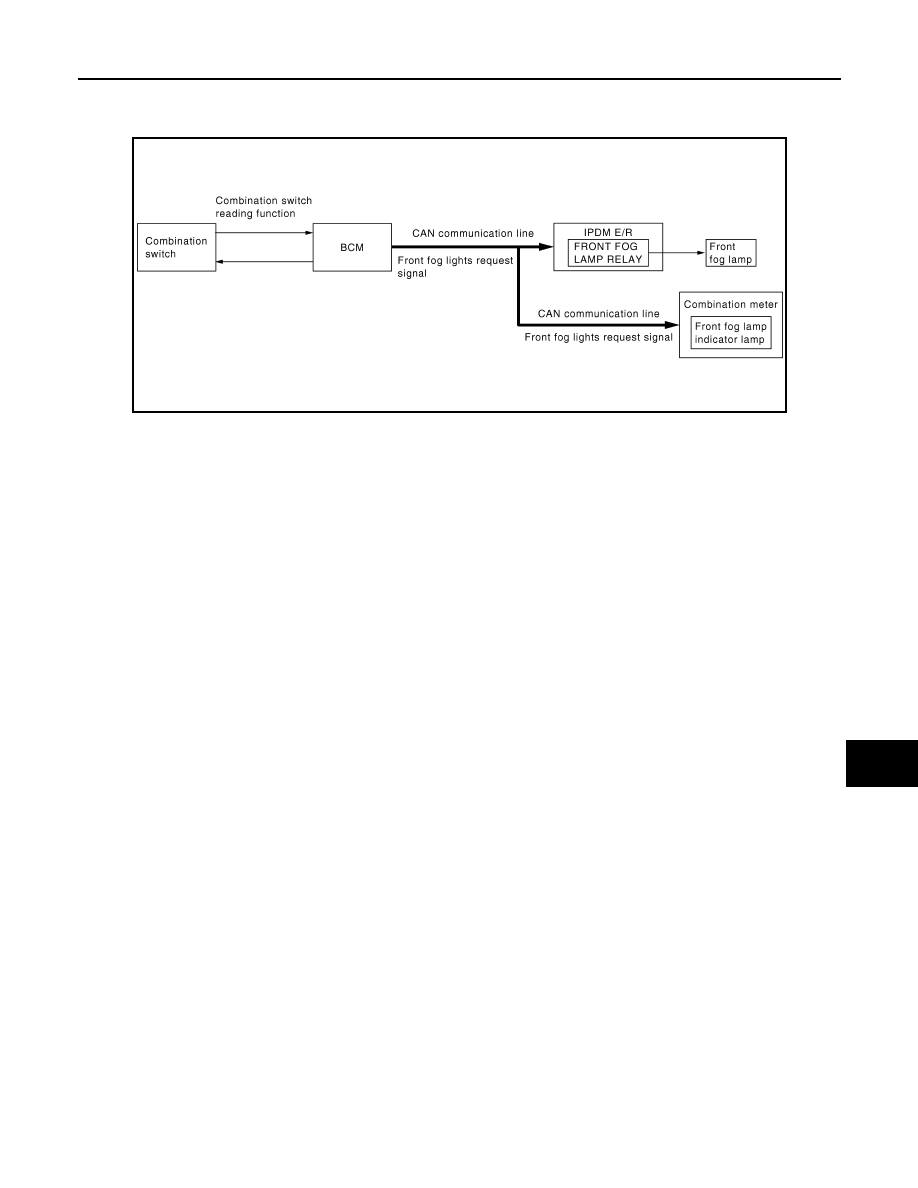
System Diagram
INFOID:0000000000955380
System Description
INFOID:0000000000955381
OUTLINE
Front fog lamp is controlled by combination switch reading function and front fog lamp control function of BCM,
and relay control function of IPDM E/R.
FRONT FOG LAMP OPERATION
• BCM detects the combination switch condition by the combination switch reading function.
• BCM transmits the front fog lights request signal to IPDM E/R and the combination meter with CAN commu-
nication according to the front fog lamp ON condition.
Front fog lamp ON condition
- Front fog lamp switch ON
- Lighting switch 1ST, 2ND, or AUTO (ignition switch ON)
• IPDM E/R turns the integrated front fog lamp relay ON, and turns the front fog lamp ON according to the
front fog lights request signal.
• Combination meter turns the front fog lamp indicator lamp ON according to the front fog lights request signal.
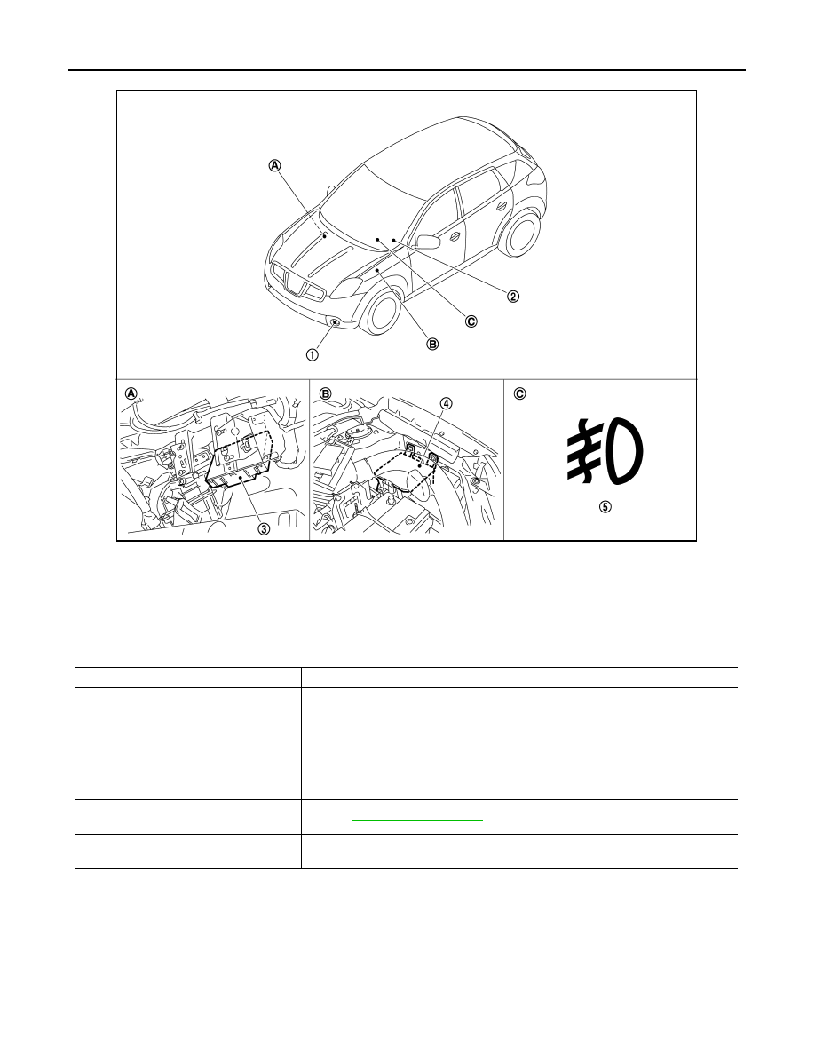
Component Parts Location
INFOID:0000000000955382
JPLIA0178GB
EXL-18
< FUNCTION DIAGNOSIS >
[XENON TYPE]
FRONT FOG LAMP SYSTEM
Component Description
INFOID:0000000000955383
1.
Front fog lamp
2.
Combination switch
3.
BCM
4.
IPDM E/R
5.
Front fog lamp indicator lamp
A.
Over the glove box
B.
Engine room (left side)
C.
On the combination meter
JPLIA0195ZZ
Part
Description
BCM
• Detects each switch condition by the combination switch reading function.
• Judges the front fog lamp ON/OFF status according to the vehicle condition.
- Requests the front fog lamp relay ON to IPDM E/R (with CAN communication).
- Requests the front fog lamp indicator lamp ON to the combination meter (with CAN
communication).
IPDM E/R
Controls the integrated relay and supplies voltage to the load according to the request
from BCM (with CAN communication).
Combination switch
(Lighting & turn signal switch)
Refer to
.
Combination meter
(Front fog lamp indicator lamp)
Turns the front fog lamp indicator lamp ON according to the request from BCM.
HEADLAMP AIMING CONTROL SYSTEM (AUTO)
EXL-19
< FUNCTION DIAGNOSIS >
[XENON TYPE]
C
D
E
F
G
H
I
J
K
M
A
B
EXL
N
O
P
HEADLAMP AIMING CONTROL SYSTEM (AUTO)
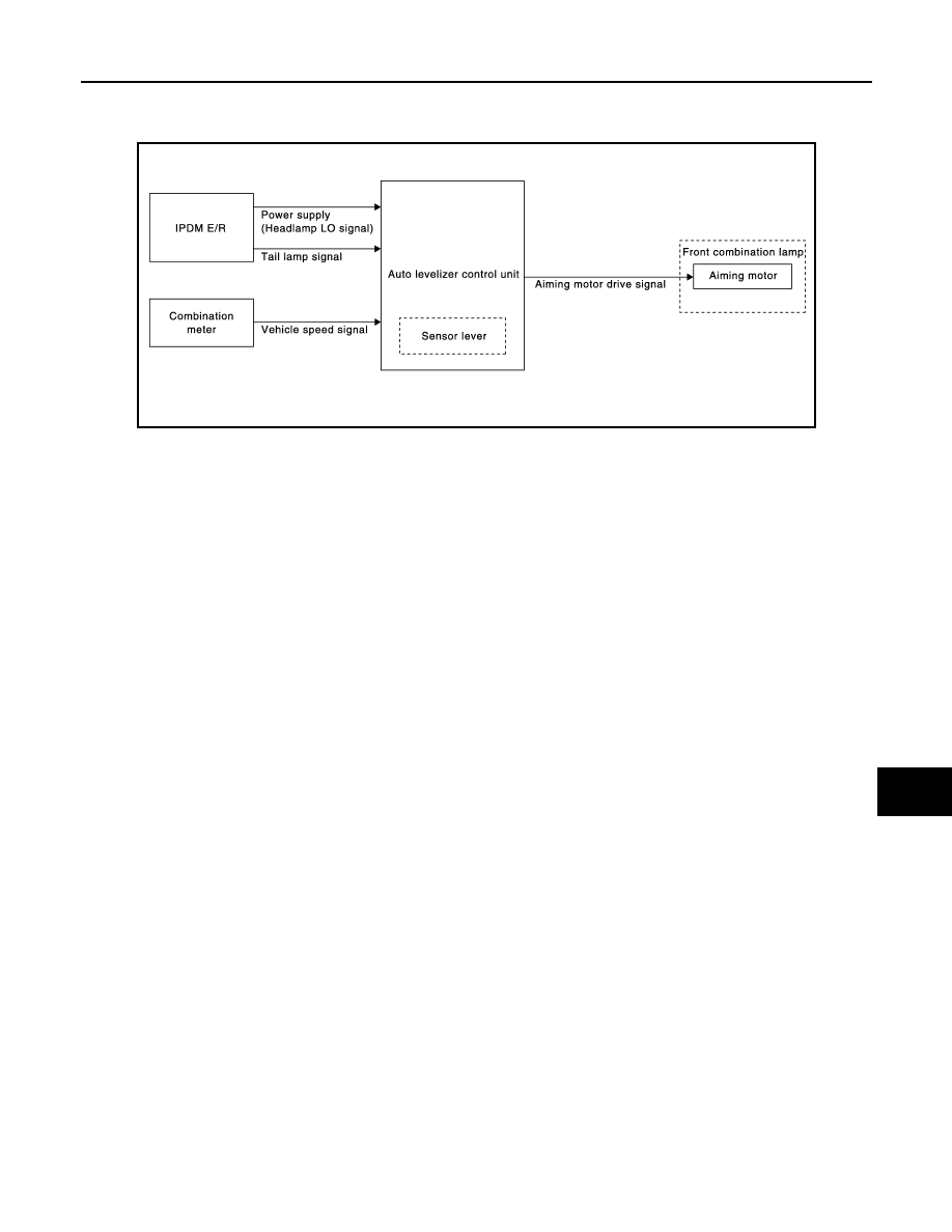
System Diagram
INFOID:0000000000955384
System Description
INFOID:0000000000955385
OUTLINE
• Headlamp aiming control system is controlled by auto levelizer control unit.
• Auto levelizer control unit controls the headlamp light axis height appropriately depending on the vehicle rear
height.
• Auto levelizer control unit detects the vehicle condition necessary for the aiming motor control with the fol-
lowing signals.
- Sensor lever signal (detected by the sensor lever)
- Tail lamp signal (inputted from IPDM E/R)
- Vehicle speed signal (8-pulse) (inputted from combination meter)
HEADLAMP AUTO AIMING OPERATION
• Auto levelizer control unit calculates vehicle pitch angle from sensor lever signal and determines the neces-
sary correction to compensate the deviation from standard light axis position.
• Auto levelizer control unit outputs aiming motor drive signal when operating conditions are satisfied.
Operating condition
- Headlamp (LO) ON
- Tail lamp ON
• Auto levelizer control unit changes the aiming motor drive signal when any of the correcting condition is
detected. Output is maintained if other condition is detected.
Correcting condition
- Headlamp (LO) is turned ON.
- Vehicle posture becomes stable after the vehicle posture change is detected with the headlamp (LO) ON
and the vehicle stopped.
- Vehicle speed is maintained with the headlamp (LO) ON and the vehicle driven.
CAUTION:
Adjusted axis position may differ from the preset position although the headlamp auto aiming acti-
vates properly when the suspension is replaced or worn.
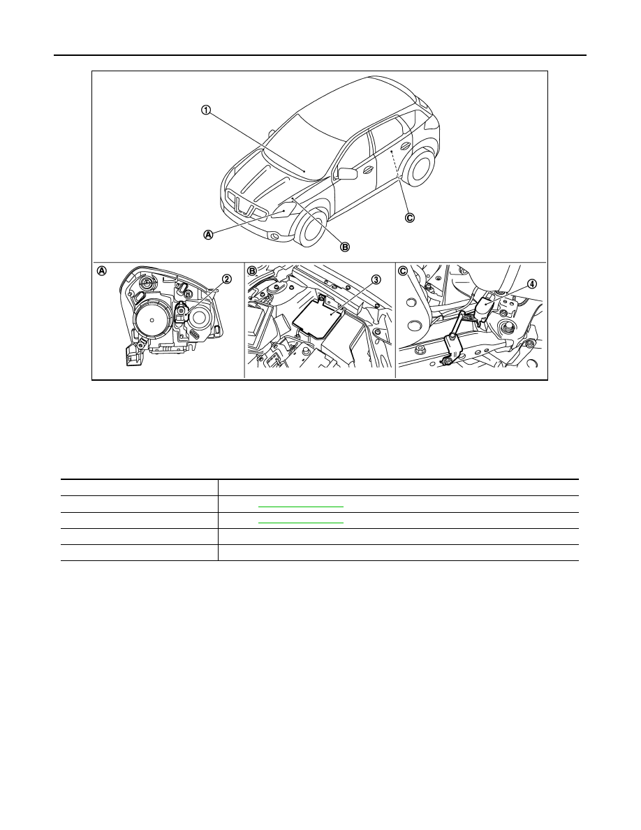
Component Parts Location
INFOID:0000000000955386
JSLIA0097GB
EXL-20
< FUNCTION DIAGNOSIS >
[XENON TYPE]
HEADLAMP AIMING CONTROL SYSTEM (AUTO)
Component Description
INFOID:0000000000955387
1.
Combination meter
2.
Aiming motor
3.
IPDM E/R
4.
Auto levelizer control unit
A.
Front combination lamp (back)
B.
Engine room (left side)
C.
Right rear suspension member
JPLIA0182ZZ
Part
Description
Auto levelizer control unit
Refer to
Headlamp aiming motor
Refer to
IPDM E/R
Outputs the tail lamp signal to auto levelizer control unit.
Combination meter
Outputs the vehicle speed signal (8-pulse) to auto levelizer control unit.
Нет комментариевНе стесняйтесь поделиться с нами вашим ценным мнением.
Текст