Nissan Qashqai (2007-2010). Manual — part 510
STR-26
< ON-VEHICLE REPAIR >
STARTER MOTOR
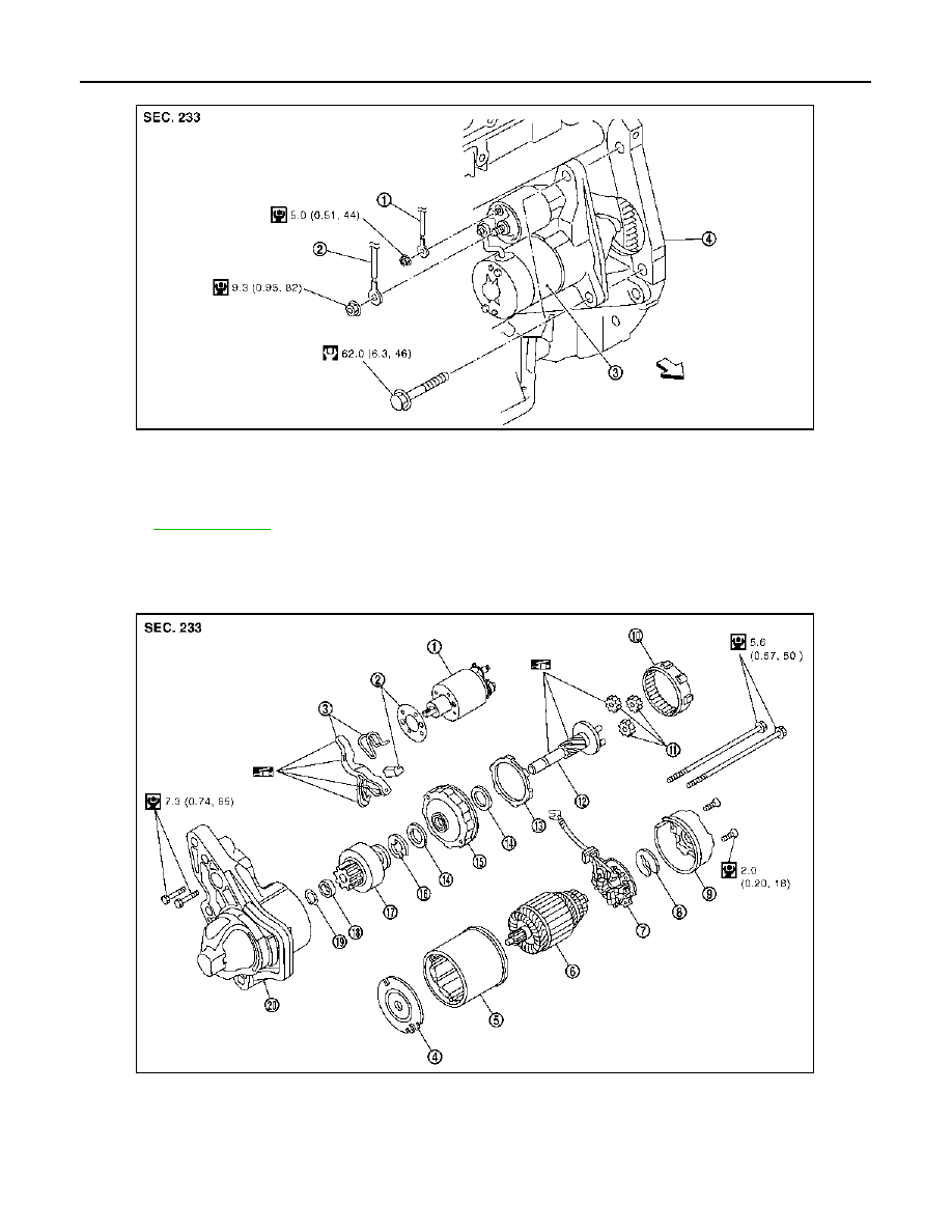
DISASSEMBLY
Type: S114-902A
1.
“S” terminal harness
2.
“B” terminal harness
3.
Starter motor
4.
Cylinder block
: Engine front
Refer to
for symbols in the figure.
PKIC8095E
1.
Magnetic switch assembly
2.
Dust cover kit
3.
Shift lever set
4.
Center bracket (A)
5.
Yoke assembly
6.
Armature assembly
7.
Brush holder assembly
8.
Thrust washer
9.
Rear cover assembly
10. Internal gear
11.
Planetary gear
12. Pinion shaft
JPBIA0549GB

STARTER MOTOR
STR-27
< ON-VEHICLE REPAIR >
C
D
E
F
G
H
I
J
K
L
M
A
STR
N
P
O
MR20DE MODELS : Removal and Installation
INFOID:0000000000955723
REMOVAL
1.
Disconnect the battery cable from the negative terminal.
2.
Disconnect the oil pressure switch connector.
3.
Remove “B” terminal nut and “B” terminal harness.
4.
Remove “S” terminal nut and “S” terminal harness.
5.
Remove starter motor mounting bolts.
6.
Remove starter motor upward from the vehicle.
CAUTION:
Never damage oil pressure switch when removing starter motor.
INSTALLATION
Install in the reverse order of removal.
CAUTION:
Be sure to tighten “B” terminal nut carefully.
MR20DE MODELS : Disassembly and Assembly
INFOID:0000000000955724
ASSEMBLY
Apply high-temperature grease to lubricate the bearing, gears and frictional surface when assembling
the starter.
Carefully observe the following manuals.
Pinion Protrusion Length Adjustment
CLEARANCE
• With pinion driven out by magnetic switch, push pinion back to
remove slack and measure clearance “L” between the front edge
of the pinion and the pinion stopper.
• Adjust with the adjusting plate if the measurement value is not in
the specified area.
MR20DE MODELS : Inspection
INFOID:0000000000955725
13. Packing
14. Thrust washer
15. Center bracket (P)
16. E-ring
17. Pinion assembly
18. Pinion stopper
19. Pinion stopper clip
20. Gear case assembly
: High-temperature grease point
Refer to
for symbols not described on the above.
Clearance “L”
: Refer to SDS
SKIB0229E
PKID0786E

STR-28
< ON-VEHICLE REPAIR >
STARTER MOTOR
INSPECTION
Magnetic Switch Check
• Before starting to check, disconnect the battery cable from the negative terminal.
• Disconnect “M” terminal of starter motor.
1.
Continuity test [between “S” terminal (A) and switch body]
• Replace magnetic switch if continuity does not exist.
2.
Continuity test [between “S” terminal (A) and “M” terminal (C)]
• Replace magnetic switch if continuity does not exist.
Pinion/Clutch Check
1.
Inspect pinion teeth.
• Replace pinion if teeth are worn or damaged. (Also check con-
dition of ring gear teeth.)
2.
Inspect reduction gear teeth (If equipped).
• Replace reduction gear if teeth are worn or damaged. (Also
check condition of armature shaft gear teeth.)
3.
Check to see if pinion locks in one direction and rotates
smoothly in the opposite direction.
• Replace pinion assembly if it is locked or rotated in both direc-
tions or unusual resistance is evident.
Brush Check
• Check wear of brush.
• Replace brush if the measurement value is less than the specified
value.
Brush Spring Check
B
: “B” terminal
C
: “M” terminal
SKIB9002E
B
: “B” terminal
SKIB9003E
SEL630BA
Minimum length of brush
: Refer to SDS
SEL014Z

STARTER MOTOR
STR-29
< ON-VEHICLE REPAIR >
C
D
E
F
G
H
I
J
K
L
M
A
STR
N
P
O
• Check brush spring tension with brush spring detached from
brush.
• Replace brush spring if the measurement value is less than the
specified value.
Brush Holder Check
1.
Perform insulation test between brush holder (positive side) and
its base (negative side).
• Replace brush holder assembly if continuity does not exist.
2.
Check brush to see if it moves smoothly.
• If brush holder is bent, replace it; if sliding surface is dirty,
clean.
Yoke Check
Magnet is secured to yoke by bonding agent. Check magnet to see
that it is secured to yoke and for any cracks. Replace malfunctioning
parts as an assembly.
CAUTION:
Never clamp yoke in a vise or strike it with a hammer.
Armature Check
1.
Continuity test (between two segments side by side)
• Replace armature assembly if continuity does not exist.
2.
Insulation test (between each commutator bar and shaft)
• Replace armature assembly if continuity exists.
Spring tension (with new
brush)
: Refer to SDS
SEL015Z
SKIB0460E
SEL305H
SKIB0461E
Нет комментариевНе стесняйтесь поделиться с нами вашим ценным мнением.
Текст