Nissan Qashqai (2007-2010). Manual — part 508

STR-18
< SYMPTOM DIAGNOSIS >
STARTING SYSTEM
SYMPTOM DIAGNOSIS
STARTING SYSTEM
Symptom Table
INFOID:0000000000955272
Symptom
Reference
No normal cranking
Refer to
STR-2, "K9K MODELS : Work Flow"
(K9K models) or
STR-4, "HR16DE/MR20DE MODELS : Work Flow"
MR20DE models).
Starter motor does not rotate
PRECAUTIONS
STR-19
< PRECAUTION >
C
D
E
F
G
H
I
J
K
L
M
A
STR
N
P
O
PRECAUTION
PRECAUTIONS
Supplemental Restraint System (SRS) "AIR BAG" and "SEAT BELT PRE-TENSION-
ER"
INFOID:0000000000955273
The Supplemental Restraint System such as “AIR BAG” and “SEAT BELT PRE-TENSIONER”, used along
with a front seat belt, helps to reduce the risk or severity of injury to the driver and front passenger for certain
types of collision. This system includes seat belt switch inputs and dual stage front air bag modules. The SRS
system uses the seat belt switches to determine the front air bag deployment, and may only deploy one front
air bag, depending on the severity of a collision and whether the front occupants are belted or unbelted.
Information necessary to service the system safely is included in the SRS and SB section of this Service Man-
ual.
WARNING:
• To avoid rendering the SRS inoperative, which could increase the risk of personal injury or death in
the event of a collision that would result in air bag inflation, all maintenance must be performed by
an authorized NISSAN/INFINITI dealer.
• Improper maintenance, including incorrect removal and installation of the SRS, can lead to personal
injury caused by unintentional activation of the system. For removal of Spiral Cable and Air Bag
Module, see the SRS section.
• Do not use electrical test equipment on any circuit related to the SRS unless instructed to in this
Service Manual. SRS wiring harnesses can be identified by yellow and/or orange harnesses or har-
ness connectors.

STR-20
< ON-VEHICLE REPAIR >
STARTER MOTOR
ON-VEHICLE REPAIR
STARTER MOTOR
K9K MODELS
K9K MODELS : Exploded View
INFOID:0000000000955275
REMOVAL
K9K MODELS : Removal and Installation
INFOID:0000000000955276
REMOVAL
1.
Disconnect the battery cable from the negative terminal.
2.
Remove “S” terminal nut and “S” terminal harness.
3.
Remove “B” terminal nut and “B” terminal harness.
4.
Remove starter motor mounting bolts.
5.
Remove starter motor upward from the vehicle.
INSTALLATION
Install in the reverse order of removal.
CAUTION:
Be sure to tighten “B” terminal nut carefully.
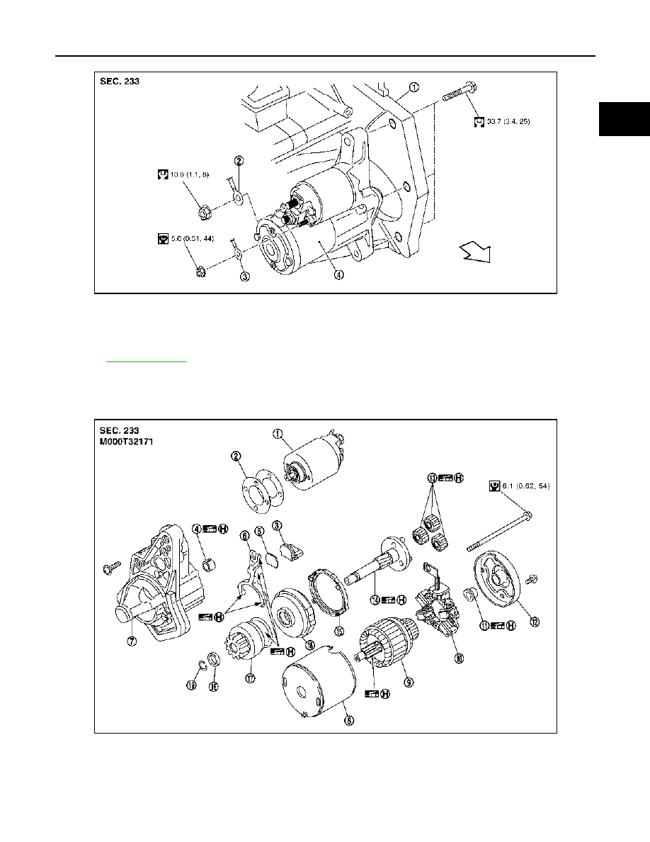
HR16DE MODELS
HR16DE MODELS : Exploded View
INFOID:0000000000955718
REMOVAL
1.
“S” terminal nut
2.
“B” terminal nut
3.
Starter motor
4.
Starter motor mounting bolt
: Engine front
Refer to
for symbols in the figure.
JPBIA0519GB
STARTER MOTOR
STR-21
< ON-VEHICLE REPAIR >
C
D
E
F
G
H
I
J
K
L
M
A
STR
N
P
O
DISASSEMBLY
Type: M000T32171
1.
Cylinder block
2.
“B” terminal harness
3.
“S” terminal harness
4.
Starter motor
: Engine front
Refer to
PKIC0987E
1.
Magnetic switch assembly
2.
Adjusting plate
3.
Packing
4.
Metal FR
5.
Plate
6.
Shift lever
7.
Gear case
8.
Yoke
9.
Armature
10. Brush holder assembly
11.
Metal RR
12. Rear cover
PKIC4906E
Нет комментариевНе стесняйтесь поделиться с нами вашим ценным мнением.
Текст