Nissan Qashqai (2007-2010). Manual — part 1671
LAN
MAIN LINE BETWEEN ABS AND TCM CIRCUIT
LAN-709
< COMPONENT DIAGNOSIS >
[CAN SYSTEM (TYPE 47)]
C
D
E
F
G
H
I
J
K
L
B
A
O
P
N
COMPONENT DIAGNOSIS
MAIN LINE BETWEEN ABS AND TCM CIRCUIT
Diagnosis Procedure
INFOID:0000000001099528
INSPECTION PROCEDURE
1.
CHECK HARNESS CONTINUITY (OPEN CIRCUIT)
1.
Turn the ignition switch OFF.
2.
Disconnect the battery cable from the negative terminal.
3.
Disconnect the following harness connectors.
-
ECM
-
ABS actuator and electric unit (control unit)
-
Harness connectors E7 and F121
4.
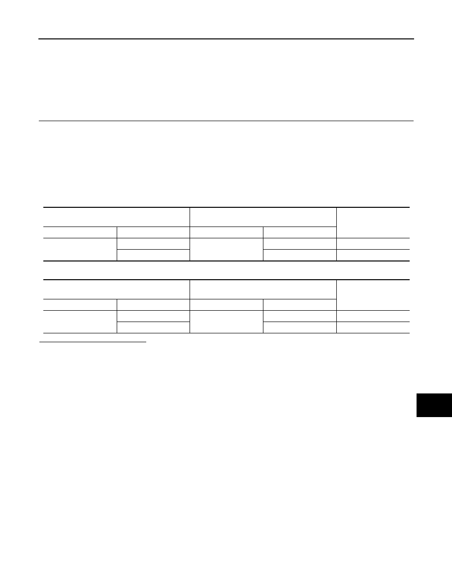
Check the continuity between the ABS actuator and electric unit (control unit) harness connector and the
harness connector.
-
Models with ESP
-
Models with ABS
Is the inspection result normal?
YES (Present error)>>Check CAN system type decision again.
YES (Past error)>>Error was detected in the main line between the ABS actuator and electric unit (control
unit) and the harness connector E7.
NO
>> Repair the main line between the ABS actuator and electric unit (control unit) and the TCM.
ABS actuator and electric unit (control unit)
harness connector
Harness connector
Continuity
Connector No.
Terminal No.
Connector No.
Terminal No.
E36
26
E7
2
Existed
15
1
Existed
ABS actuator and electric unit (control unit)
harness connector
Harness connector
Continuity
Connector No.
Terminal No.
Connector No.
Terminal No.
E34
26
E7
2
Existed
15
1
Existed
LAN-710
< COMPONENT DIAGNOSIS >
[CAN SYSTEM (TYPE 47)]
MAIN LINE BETWEEN TCM AND DLC CIRCUIT
MAIN LINE BETWEEN TCM AND DLC CIRCUIT
Diagnosis Procedure
INFOID:0000000001099532
INSPECTION PROCEDURE
1.
CHECK CONNECTOR
1.
Turn the ignition switch OFF.
2.
Disconnect the battery cable from the negative terminal.
3.
Check the following terminals and connectors for damage, bend and loose connection (connector side
and harness side).
-
Harness connector E105
-
Harness connector M77
Is the inspection result normal?
YES
>> GO TO 2.
NO
>> Repair the terminal and connector.
2.
CHECK HARNESS CONTINUITY (OPEN CIRCUIT)
1.
Disconnect the following harness connectors.
-
Harness connectors F121 and E7
-
Harness connectors E105 and M77
2.
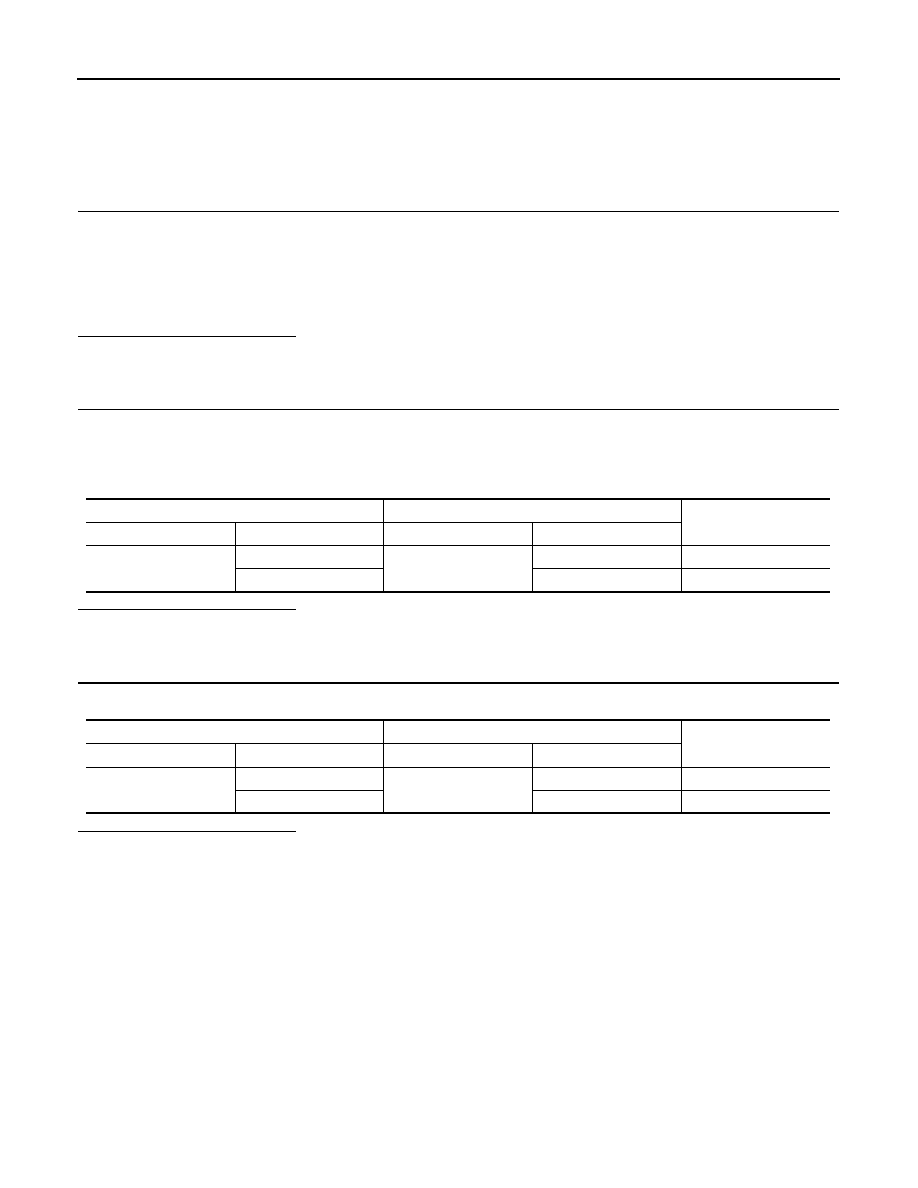
Check the continuity between the harness connectors.
Is the inspection result normal?
YES
>> GO TO 3.
NO
>> Repair the main line between the harness connector E7 and the harness connector E105.
3.
CHECK HARNESS CONTINUITY (OPEN CIRCUIT)
Check the continuity between the harness connector and the data link connector.
Is the inspection result normal?
YES (Present error)>>Check CAN system type decision again.
YES (Past error)>>Error was detected in the main line between the TCM and the data link connector.
NO
>> Repair the main line between the harness connector M77 and the data link connector.
Harness connector
Harness connector
Continuity
Connector No.
Terminal No.
Connector No.
Terminal No.
E7
2
E105
52
Existed
1
51
Existed
Harness connector
Data link connector
Continuity
Connector No.
Terminal No.
Connector No.
Terminal No.
M77
52
M4
6
Existed
51
14
Existed
L A N
MAIN LINE BETWEEN DLC AND BCM CIRCUIT
LAN-711
< COMPONENT DIAGNOSIS >
[CAN SYSTEM (TYPE 47)]
C
D
E
F
G
H
I
J
K
L
B
A
O
P
N
MAIN LINE BETWEEN DLC AND BCM CIRCUIT
Diagnosis Procedure
INFOID:0000000001099533
INSPECTION PROCEDURE
1.
CHECK HARNESS CONTINUITY (OPEN CIRCUIT)
1.
Turn the ignition switch OFF.
2.
Disconnect the battery cable from the negative terminal.
3.
Disconnect the following harness connectors.
-
ECM
-
BCM
4.
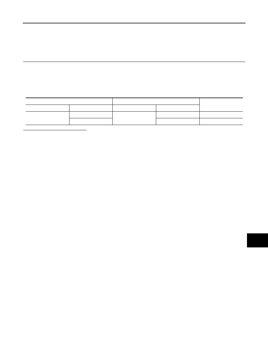
Check the continuity between the data link connector and the BCM harness connector.
Is the inspection result normal?
YES (Present error)>>Check CAN system type decision again.
YES (Past error)>>Error was detected in the main line between the data link connector and the BCM.
NO
>> Repair the main line between the data link connector and the BCM.
Data link connector
BCM harness connector
Continuity
Connector No.
Terminal No.
Connector No.
Terminal No.
M4
6
M65
19
Existed
14
20
Existed
LAN-712
< COMPONENT DIAGNOSIS >
[CAN SYSTEM (TYPE 47)]
ECM BRANCH LINE CIRCUIT
ECM BRANCH LINE CIRCUIT
Diagnosis Procedure
INFOID:0000000001099534
1.
CHECK CONNECTOR
1.
Turn the ignition switch OFF.
2.
Disconnect the battery cable from the negative terminal.
3.
Check the terminals and connectors of the ECM for damage, bend and loose connection (unit side and
connector side).
Is the inspection result normal?
YES
>> GO TO 2.
NO
>> Repair the terminal and connector.
2.
CHECK HARNESS FOR OPEN CIRCUIT
1.
Disconnect the connector of ECM.
2.
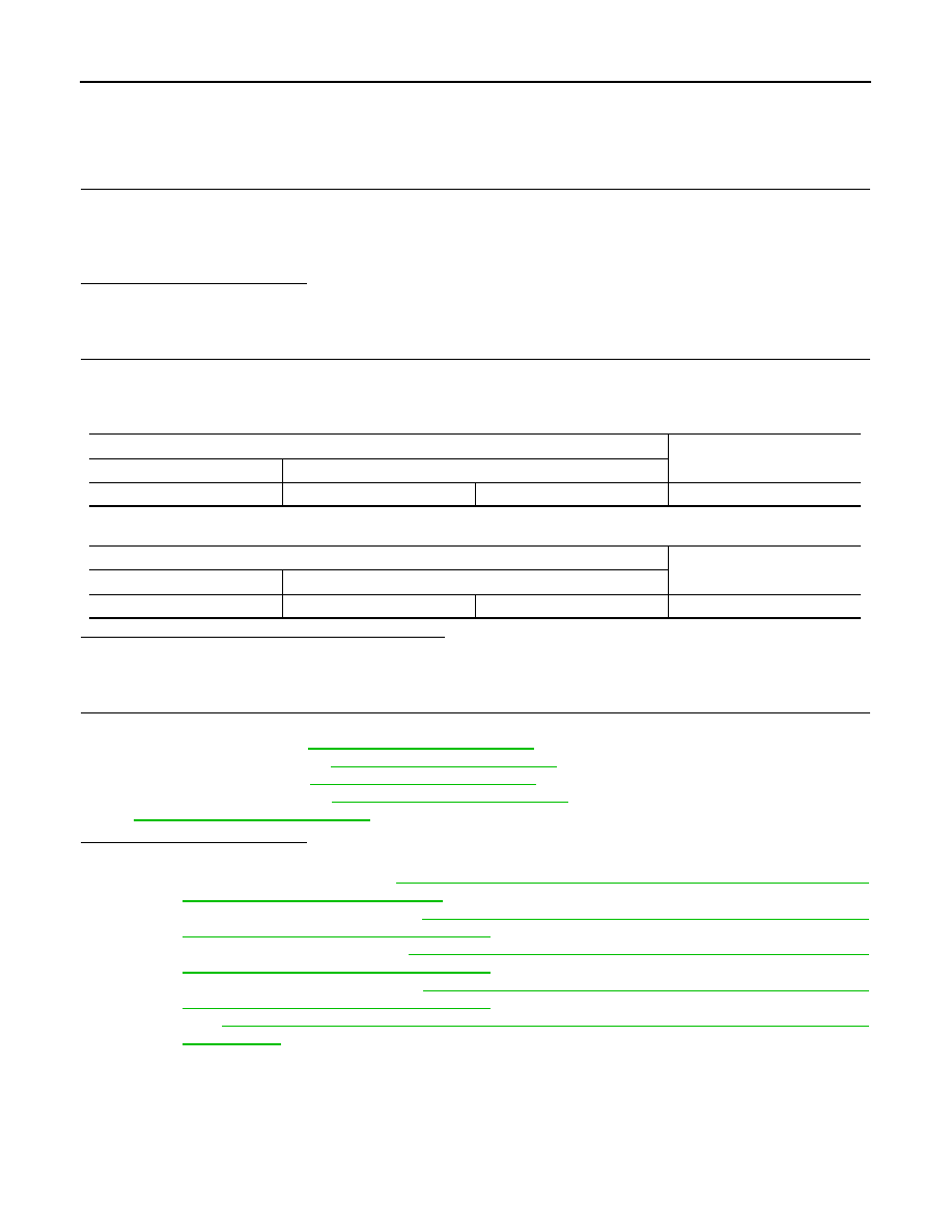
Check the resistance between the ECM harness connector terminals.
-
HR engine/MR engine models
-
K9K engine models
Is the measurement value within the specification?
YES
>> GO TO 3.
NO
>> Repair the ECM branch line.
3.
CHECK POWER SUPPLY AND GROUND CIRCUIT
Check the power supply and the ground circuit of the ECM. Refer to the following.
• HR16DE (With EURO-OBD):
• HR16DE (Without EURO-OBD):
• MR20DE (With EURO-OBD):
• MR20DE (Without EURO-OBD):
EC-1069, "Diagnosis Procedure"
EC-1317, "Diagnosis Procedure"
Is the inspection result normal?
YES (Present error)>>•Replace the ECM. Refer to the following.
- HR16DE (With EURO-OBD):
EC-29, "ADDITIONAL SERVICE WHEN REPLACING CONTROL
UNIT : Special Repair Requirement"
- HR16DE (Without EURO-OBD):
EC-368, "ADDITIONAL SERVICE WHEN REPLACING CON-
TROL UNIT : Special Repair Requirement"
- MR20DE (With EURO-OBD):
EC-645, "ADDITIONAL SERVICE WHEN REPLACING CON-
TROL UNIT : Special Repair Requirement"
- MR20DE (Without EURO-OBD):
EC-989, "ADDITIONAL SERVICE WHEN REPLACING CON-
TROL UNIT : Special Repair Requirement"
EC-1273, "ADDITIONAL SERVICE WHEN REPLACING CONTROL UNIT : Special Repair
YES (Past error)>>Error was detected in the ECM branch line.
NO
>> Repair the power supply and the ground circuit.
ECM harness connector
Resistance (
Ω
)
Connector No.
Terminal No.
E16
84
83
Approx. 108 – 132
ECM harness connector
Resistance (
Ω
)
Connector No.
Terminal No.
E60
100
99
Approx. 108 – 132
Нет комментариевНе стесняйтесь поделиться с нами вашим ценным мнением.
Текст