Nissan Qashqai (2007-2010). Manual — part 1672
LAN
ABS BRANCH LINE CIRCUIT
LAN-713
< COMPONENT DIAGNOSIS >
[CAN SYSTEM (TYPE 47)]
C
D
E
F
G
H
I
J
K
L
B
A
O
P
N
ABS BRANCH LINE CIRCUIT
Diagnosis Procedure
INFOID:0000000001099535
1.
CHECK CONNECTOR
1.
Turn the ignition switch OFF.
2.
Disconnect the battery cable from the negative terminal.
3.
Check the terminals and connectors of the ABS actuator and electric unit (control unit) for damage, bend
and loose connection (unit side and connector side).
Is the inspection result normal?
YES
>> GO TO 2.
NO
>> Repair the terminal and connector.
2.
CHECK HARNESS FOR OPEN CIRCUIT
1.
Disconnect the connector of ABS actuator and electric unit (control unit).
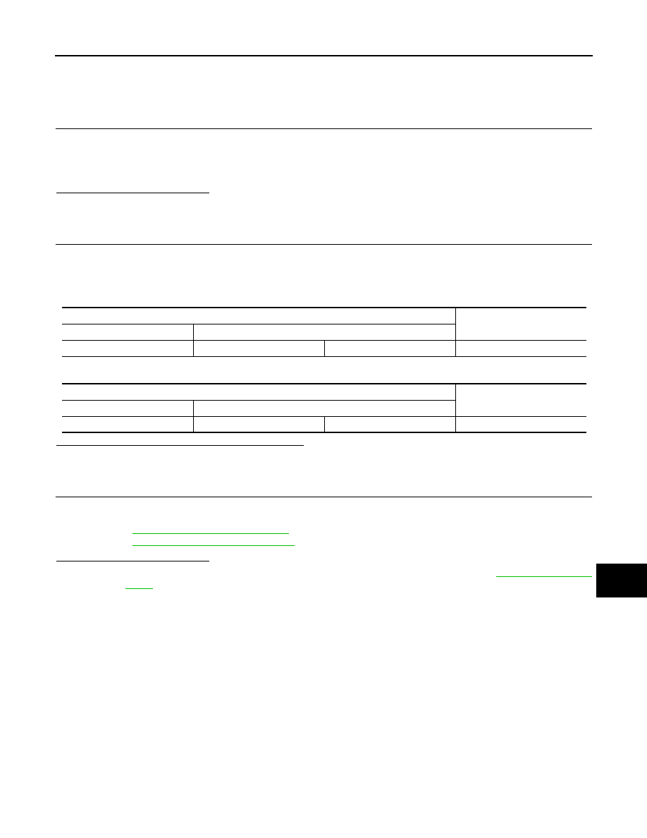
2.
Check the resistance between the ABS actuator and electric unit (control unit) harness connector termi-
nals.
-
Models with ESP
-
Models with ABS
Is the measurement value within the specification?
YES
>> GO TO 3.
NO
>> Repair the ABS actuator and electric unit (control unit) branch line.
3.
CHECK POWER SUPPLY AND GROUND CIRCUIT
Check the power supply and the ground circuit of the ABS actuator and electric unit (control unit). Refer to the
following.
• ABS models:
• ESP models:
BRC-106, "Diagnosis Procedure"
Is the inspection result normal?
YES (Present error)>>•Replace the ABS actuator and electric unit (control unit). Refer to
.
YES (Past error)>>Error was detected in the ABS actuator and electric unit (control unit) branch line.
NO
>> Repair the power supply and the ground circuit.
ABS actuator and electric unit (control unit) harness connector
Resistance (
Ω
)
Connector No.
Terminal No.
E36
26
15
Approx. 54 – 66
ABS actuator and electric unit (control unit) harness connector
Resistance (
Ω
)
Connector No.
Terminal No.
E34
26
15
Approx. 54 – 66
LAN-714
< COMPONENT DIAGNOSIS >
[CAN SYSTEM (TYPE 47)]
TCM BRANCH LINE CIRCUIT
TCM BRANCH LINE CIRCUIT
Diagnosis Procedure
INFOID:0000000001099536
1.
CHECK CONNECTOR
1.
Turn the ignition switch OFF.
2.
Disconnect the battery cable from the negative terminal.
3.
Check the following terminals and connectors for damage, bend and loose connection (unit side and con-
nector side).
-
TCM
-
Harness connector F121
-
Harness connector E7
Is the inspection result normal?
YES
>> GO TO 2.
NO
>> Repair the terminal and connector.
2.
CHECK HARNESS FOR OPEN CIRCUIT
1.
Disconnect the connector of TCM.
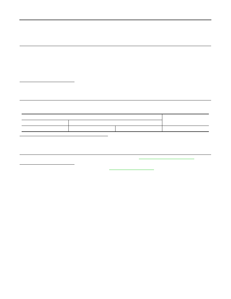
2.
Check the resistance between the TCM harness connector terminals.
Is the measurement value within the specification?
YES
>> GO TO 3.
NO
>> Repair the TCM branch line.
3.
CHECK POWER SUPPLY AND GROUND CIRCUIT
Check the power supply and the ground circuit of the TCM. Refer to
Is the inspection result normal?
YES (Present error)>>Replace the TCM. Refer to
YES (Past error)>>Error was detected in the TCM branch line.
NO
>> Repair the power supply and the ground circuit.
TCM harness connector
Resistance (
Ω
)
Connector No.
Terminal No.
F25
32
31
Approx. 54 – 66
LAN
4WD BRANCH LINE CIRCUIT
LAN-715
< COMPONENT DIAGNOSIS >
[CAN SYSTEM (TYPE 47)]
C
D
E
F
G
H
I
J
K
L
B
A
O
P
N
4WD BRANCH LINE CIRCUIT
Diagnosis Procedure
INFOID:0000000001099537
1.
CHECK CONNECTOR
1.
Turn the ignition switch OFF.
2.
Disconnect the battery cable from the negative terminal.
3.
Check the terminals and connectors of the 4WD control unit connector for damage, bend and loose con-
nection (unit side and connector side).
Is the inspection result normal?
YES
>> GO TO 2.
NO
>> Repair the terminal and connector.
2.
CHECK HARNESS FOR OPEN CIRCUIT
1.
Disconnect the connector of 4WD control unit.
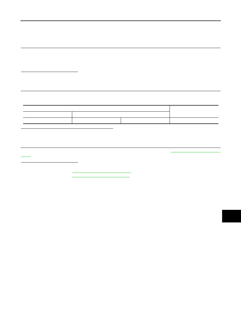
2.
Check the resistance between the 4WD control unit harness connector terminals.
Is the measurement value within the specification?
YES
>> GO TO 3.
NO
>> Repair the 4WD control unit branch line.
3.
CHECK POWER SUPPLY AND GROUND CIRCUIT
Check the power supply and the ground circuit of the 4WD control unit. Refer to
.
Is the inspection result normal?
YES (Present error)>>•Replace the 4WD control unit. Refer to the following.
- RHD models:
- LHD models:
YES (Past error)>>Error was detected in the 4WD control unit branch line.
NG
>> Repair the power supply and the ground circuit.
4WD control unit harness connector
Resistance (
Ω
)
Connector No.
Terminal No.
M69
8
16
Approx. 54 – 66
LAN-716
< COMPONENT DIAGNOSIS >
[CAN SYSTEM (TYPE 47)]
BCM BRANCH LINE CIRCUIT
BCM BRANCH LINE CIRCUIT
Diagnosis Procedure
INFOID:0000000001099538
1.
CHECK CONNECTOR
1.
Turn the ignition switch OFF.
2.
Disconnect the battery cable from the negative terminal.
3.
Check the terminals and connectors of the BCM for damage, bend and loose connection (unit side and
connector side).
Is the inspection result normal?
YES
>> GO TO 2.
NO
>> Repair the terminal and connector.
2.
CHECK HARNESS FOR OPEN CIRCUIT
1.
Disconnect the connector of BCM.
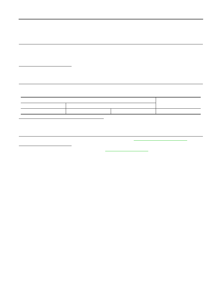
2.
Check the resistance between the BCM harness connector terminals.
Is the measurement value within the specification?
YES
>> GO TO 3.
NO
>> Repair the BCM branch line.
3.
CHECK POWER SUPPLY AND GROUND CIRCUIT
Check the power supply and the ground circuit of the BCM. Refer to
Is the inspection result normal?
YES (Present error)>>Replace the BCM. Refer to
.
YES (Past error)>>Error was detected in the BCM branch line.
NO
>> Repair the power supply and the ground circuit.
BCM harness connector
Resistance (
Ω
)
Connector No.
Terminal No.
M65
19
20
Approx. 54 – 66
Нет комментариевНе стесняйтесь поделиться с нами вашим ценным мнением.
Текст