Nissan Qashqai (2007-2010). Manual — part 569

SHIFT LOCK SYSTEM
TM-211
< FUNCTION DIAGNOSIS >
[CVT: RE0F10A]
C
E
F
G
H
I
J
K
L
M
A
B
TM
N
O
P
SHIFT LOCK SYSTEM
System Description
INFOID:0000000000914573
It is designed so that it cannot be shifted from the P position unless
the brake pedal is depressed while the ignition switch is set to ON.
The shift lock is unlocked by turning the shift lock solenoid ON when
the ignition switch is set to ON, the park switch is turned ON (selec-
tor lever is in P position), and the stop lamp switch is turned ON
(brake pedal is depressed) as shown in the operation chart in the fig-
ure. Therefore, the shift lock solenoid receives no ON signal and the
shift lock remains locked if all of the above conditions are not ful-
filled. (However, selector operation is allowed if the shift lock release
button is pressed.)
SHIFT LOCK OPERATION at P POSITION
When Brake Pedal Is Not Depressed (No Selector Operation Allowed)
The shift lock solenoid (1) is turned OFF (not energized) and the
solenoid rod (A) is extended with the spring when the brake pedal is
not depressed (no selector operation allowed) with the ignition
switch ON.
The connecting lock lever (B) is located at the position shown in the
figure when the solenoid rod is extended. It prevents the movement
of the detent rod (C). The selector lever cannot be shifted from the P
position for this reason. However, the lock lever is forcibly moved to
the direction opposite to that of the arrow when the shift lock release
button (D) is pressed. Selector operation can be performed.
When Brake Pedal Is Depressed (Shift Operation Allowed)
The shift lock solenoid (1) is turned ON (energized) when the brake
pedal is depressed with the ignition switch ON. The solenoid rod (A)
is compressed with the electromagnetic force. The connecting lock
lever (B) rotates when the solenoid is compressed. Therefore, the
detent rod (C) can be moved. The selector lever can be shifted to
other positions for this reason.
P POSITION HOLD MECHANISM (IGNITION SWITCH LOCK)
JPDIA0183GB
JPDIA0110ZZ
JPDIA0111ZZ
TM-212
< FUNCTION DIAGNOSIS >
[CVT: RE0F10A]
SHIFT LOCK SYSTEM
The shift lock solenoid (1) is not energized when the ignition switch
is in any position other than ON. The shift mechanism is locked and
P position is held. The operation cannot be performed from P posi-
tion if the brake pedal is depressed with the ignition switch ON when
the operation system of shift lock solenoid is malfunctioning. How-
ever, the lock lever (A) is forcibly rotated and the shift lock is
released when the shift lock release button (B) is pressed from
above. The selector operation from P position can be performed.
CAUTION:
Use the shift lock release button only when the selector lever
cannot be operated even if the brake pedal is depressed with
the ignition switch ON.
KEY LOCK MECHANISM
The key is not set to LOCK when the selector lever is not selected to P position. This prevents the key from
being removed from the key cylinder.
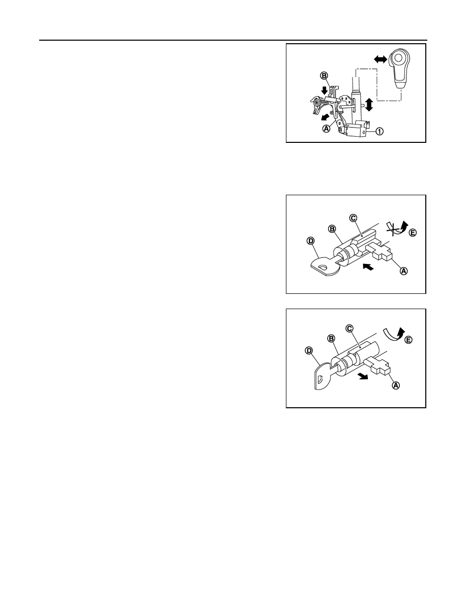
Key Lock Status
The slider (A) in the key cylinder (B) is moved to the left side of the
figure when the selector lever is in any position other than P position.
The rotator (C) that rotates together with the key (D) cannot be
rotated for this reason. The key cannot be removed from the key cyl-
inder because it cannot be turned to LOCK (E).
Key Unlock Status
The slider (A) in the key cylinder (B) is moved to the right side of the
figure when the selector lever is in P position and the finger is
removed from the selector button. The rotator (C) can be rotated for
this reason. The key (D) can be removed from the key cylinder
because it can be turned to LOCK (E).
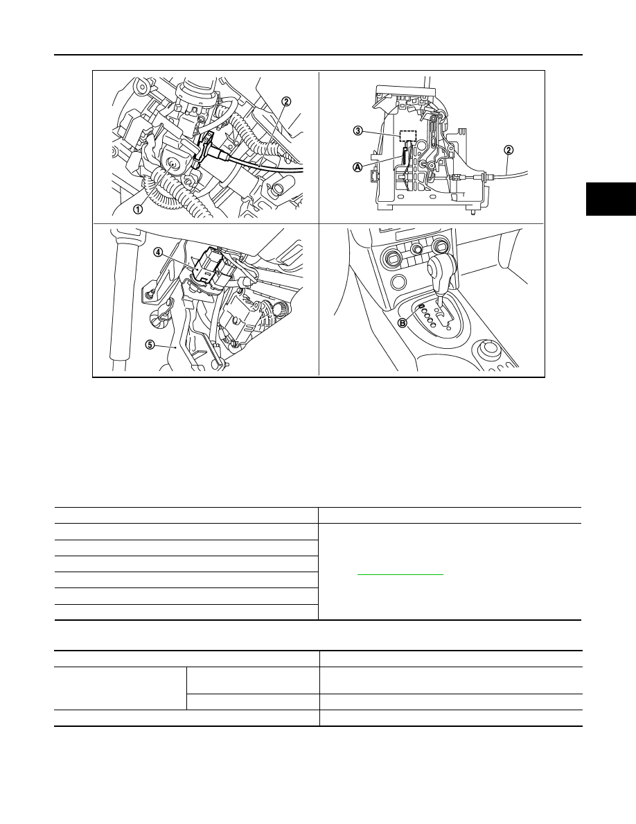
Component Parts Location
INFOID:0000000000914574
JPDIA0112ZZ
JPDIA0320ZZ
JPDIA0321ZZ
SHIFT LOCK SYSTEM
TM-213
< FUNCTION DIAGNOSIS >
[CVT: RE0F10A]
C
E
F
G
H
I
J
K
L
M
A
B
TM
N
O
P
Component Description
INFOID:0000000000927611
SHIFT LOCK
KEY LOCK
1.
Key cylinder
2.
Key interlock cable
3.
Shift lock solenoid
4.
Stop lamp switch
5.
Brake pedal
A.
Park position switch
B.
Shift lock release button*
*: Shift lock release button becomes operative by removing shift lock cover. (LHD only)
JPDIA0119ZZ
Component
Function
Shift lock solenoid
Lock lever
Detent rod
Park position switch
Key interlock cable and rod
Shift lock release button
Component
Function
Key cylinder
Rotator
It rotates together with the key and restricts the slider movement
when the ignition switch is in LOCK position.
Slider
It moves according to the rotation of the lock lever.
Key interlock cable and key interlock rod
Actuation of lock lever is conveyed to slider in the key cylinder.
TM-214
< FUNCTION DIAGNOSIS >
[CVT: RE0F10A]
ON BOARD DIAGNOSTIC (OBD) SYSTEM
ON BOARD DIAGNOSTIC (OBD) SYSTEM
Diagnosis Description
INFOID:0000000000988626
DESCRIPTION
The CVT system has two self-diagnostic systems.
The first is the emission-related on board diagnostic system (OBD) performed by the TCM in combination with
the ECM. The malfunction is indicated by the MI (malfunction indicator) and is stored as a DTC in the ECM
memory, and the TCM memory.
The second is the TCM original self-diagnosis performed by the TCM. The malfunction is stored in the TCM
memory. The detected items are overlapped with OBD self-diagnostic items. For detail, refer to
"CONSULT-III Function (TRANSMISSION)"
OBD FUNCTION
The ECM provides emission-related on board diagnostic (OBD) functions for the CVT system. One function is
to receive a signal from the TCM used with OBD-related parts of the CVT system. The signal is sent to the
ECM when a malfunction occurs in the corresponding OBD-related part. The other function is to indicate a
diagnostic result by means of the MI (malfunction indicator) on the instrument panel. Sensors, switches and
solenoid valves are used as sensing elements.
The MI automatically illuminates in “One or Two Trip Detection Logic” when a malfunction is sensed in relation
to CVT system parts.
ONE OR TWO TRIP DETECTION LOGIC OF OBD
One Trip Detection Logic
If a malfunction is sensed during the first test drive, the MI will illuminate and the malfunction will be stored in
the ECM memory as a DTC. The TCM is not provided with such a memory function.
Two Trip Detection Logic
When a malfunction is sensed during the first test drive, it is stored in the ECM memory as a 1st trip DTC
(diagnostic trouble code) or 1st trip freeze frame data. At this point, the MI will not illuminate. — 1st trip
If the same malfunction as that experienced during the first test drive is sensed during the second test drive,
the MI will illuminate. — 2nd trip
The “trip” in the “One or Two Trip Detection Logic” means a driving mode in which self-diagnosis is performed
during vehicle operation.
OBD DIAGNOSTIC TROUBLE CODE (DTC)
How to Read DTC and 1st Trip DTC
DTC and 1st trip DTC can be read by the following methods.
(
with CONSULT-III or
GST) CONSULT-III or GST (Generic Scan Tool) Examples: P0705, P0720 etc.
These DTC are prescribed by ISO 15031-5.
(CONSULT-III also displays the malfunctioning component or system.)
• 1st trip DTC No. is the same as DTC No.
• Output of the diagnostic trouble code indicates that the indicated circuit has a malfunction. How-
ever, in case of the Mode II and GST, they do not indicate whether the malfunction is still occurring or
occurred in the past and returned to normal.
CONSULT-III can identify them as shown below, therefore, CONSULT-III (if available) is recom-
mended.
- DTC or 1st trip DTC of a malfunction is displayed in SELF-DIAGNOSTIC RESULTS mode for “ENGINE” with
CONSULT-III. Time data indicates how many times the vehicle was driven after the last detection of a DTC.
- If the DTC is being detected currently, the time data will be “0”.
- If a 1st trip DTC is stored in the ECM, the time data will be “1t”.
Freeze Frame Data and 1st Trip Freeze Frame Data
• The ECM has a memory function, which stores the driving condition such as fuel system status, calculated
load value, engine coolant temperature, short term fuel trim, long term fuel trim, engine speed and vehicle
speed at the moment the ECM detects a malfunction.
Data which are stored in the ECM memory, along with the 1st trip DTC, are called 1st trip freeze frame data,
and the data, stored together with the DTC data, are called freeze frame data and displayed on CONSULT-
III or GST. The 1st trip freeze frame data can only be displayed on the CONSULT-III screen, not on the GST.
For details, refer to
EC-719, "CONSULT-III Function"
(WITH EURO-OBD),
(WITHOUT EURO-OBD).
Нет комментариевНе стесняйтесь поделиться с нами вашим ценным мнением.
Текст