Nissan Qashqai (2007-2010). Manual — part 570
ON BOARD DIAGNOSTIC (OBD) SYSTEM
TM-215
< FUNCTION DIAGNOSIS >
[CVT: RE0F10A]
C
E
F
G
H
I
J
K
L
M
A
B
TM
N
O
P
Only one set of freeze frame data (either 1st trip freeze frame data or freeze frame data) can be stored in the
ECM. 1st trip freeze frame data is stored in the ECM memory along with the 1st trip DTC. There is no priority
for 1st trip freeze frame data, and it is updated each time a different 1st trip DTC is detected. However, once
freeze frame data (2nd trip detection/MI on) is stored in the ECM memory, 1st trip freeze frame data is no
longer stored. Remember, only one set of freeze frame data can be stored in the ECM. The ECM has the fol-
lowing priorities to update the data.
Both 1st trip freeze frame data and freeze frame data (along with the DTC) are cleared when the ECM mem-
ory is erased.
How to Erase DTC
• The diagnostic trouble code can be erased by CONSULT-III, GST or ECM DIAGNOSTIC TEST MODE as
described following.
- If the battery cable is disconnected, the diagnostic trouble code will be lost within 24 hours.
- When you erase the DTC, using CONSULT-III or GST is easier and quicker than switching the mode
selector on the ECM.
• The following emission-related diagnostic information is cleared from the ECM memory when erasing DTC
related to OBD. For details, refer to
.
- Diagnostic trouble codes (DTC)
- 1st trip diagnostic trouble codes (1st trip DTC)
- Freeze frame data
- 1st trip freeze frame data
- System readiness test (SRT) codes
- Test values
How to Erase DTC (With CONSULT-III)
The emission related diagnostic information in the TCM and ECM can be erased by selecting “ALL Erase” in
the “Description” of “FINAL CHECK” mode with CONSULT-III.
How to Erase DTC (With GST)
1.
If the ignition switch stays ON after repair work, be sure to turn ignition switch OFF once. Wait at least 10
seconds and then turn it ON (engine stopped) again.
2.
Select Mode 4 with GST (Generic Scan Tool). For details, refer to
EC-719, "CONSULT-III Function"
(WITH
EURO-OBD),
EC-1054, "CONSULT-III Function"
(WITHOUT EURO-OBD).
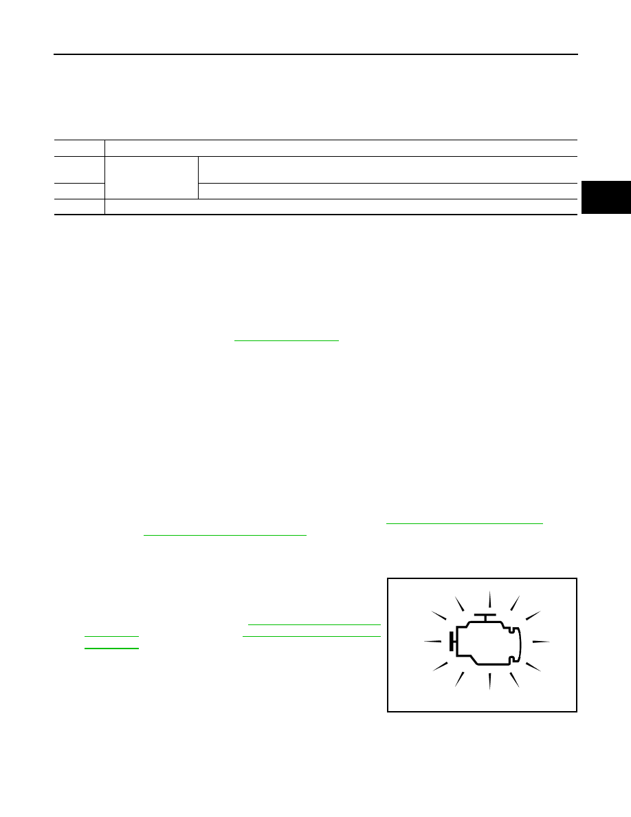
MALFUNCTION INDICATOR (MI)
Description
The MI is located on the instrument panel.
1.
The MI will light up when the ignition switch is turned ON without
the engine running. This is a bulb check.
• If the MI does not light up, refer to
(WITHOUT EURO-OBD).
2.
When the engine is started, the MI should go off.
If the MI remains on, the on board diagnostic system has
detected an engine system malfunction.
Priority
Items
1
Freeze frame data
Misfire — DTC: P0300 - P0304
Fuel Injection System Function — DTC: P0171, P0172
2
Except the above items (Includes CVT related items)
3
1st trip freeze frame data
SAT652J

TM-216
< FUNCTION DIAGNOSIS >
[CVT: RE0F10A]
DIAGNOSIS SYSTEM (TCM)
DIAGNOSIS SYSTEM (TCM)
CONSULT-III Function (TRANSMISSION)
INFOID:0000000000988627
CONSULT-III can display each diagnostic item using the diagnostic test modes shown below.
FUNCTION
WORK SUPPORT MODE
Display Item List
Engine Brake Adjustment
CAUTION:
Mode of “+1”“0”“
−
1”“
−
2”“OFF” can be selected by pressing the “UP”“DOWN” on CONSULT-III screen.
However, do not select mode other than “0” and “OFF”. If the “+1” or “
−
1” or “–2” is selected, that
might cause the irregular driveability.
Check CVT Fluid Deterioration Date
CAUTION:
Touch “CLEAR” after changing CVT fluid, and then erase “CVTF DETERIORATION DATE”.
SELF-DIAGNOSTIC RESULT MODE
After performing self-diagnosis, place check marks for results on the
TM-187, "Diagnostic Work Sheet"
. Refer-
ence pages are provided following the items.
Display Items List
Diagnostic test mode
Function
Work support
This mode enables a technician to adjust some devices faster and more accurately by following the in-
dications on CONSULT-III.
Self-diagnostic results
Self-diagnostic results can be read and erased quickly.
Data monitor
Input/Output data in the TCM can be read.
CAN diagnostic support mon-
itor
The results of transmit/receive diagnosis of CAN communication can be read.
CALIB data
Characteristic information for TCM and CVT assembly can be read. Do not use, but displayed.
Function test
Performed by CONSULT-III instead of a technician to determine whether each system is “OK” or “NG”.
ECU part number
TCM part number can be read.
Item name
Description
ENGINE BRAKE ADJ.
The engine brake level setting can be canceled.
CONFORM CVTF DETERIORTN
The CVT fluid deterioration level can be checked.
“ENGINE BRAKE LEVEL”
0:
Initial set value (Engine brake level control is activated)
OFF:
Engine brake level control is deactivated.
“CVTF DETERIORATION DATE”
More than 210000:
It is necessary to change CVT fluid.
Less than 210000:
It is not necessary to change CVT fluid.

DIAGNOSIS SYSTEM (TCM)
TM-217
< FUNCTION DIAGNOSIS >
[CVT: RE0F10A]
C
E
F
G
H
I
J
K
L
M
A
B
TM
N
O
P
X: Applicable
—: Not applicable
Items (CONSULT-
III screen terms)
Malfunction is detected when...
TCM self-di-
agnosis
OBD (DTC)
Reference
page
“TRANSMIS-
SION” with
CONSULT-III
MI
*
, “ENGINE”
with CON-
SULT-III or
GST
CAN COMM CIR-
CUIT
When TCM is not transmitting or receiving CAN communica-
tion signal for 2 seconds or more.
U1000
U1000
CONTROL UNIT
(CAN)
When detecting error during the initial diagnosis of CAN con-
troller to TCM.
U1010
U1010
BRAKE SW/CIRC
When the brake switch does not switch to ON or OFF.
P0703
—
PNP SW/CIRC
TCM does not receive the correct voltage signal (based on
the gear position) from the switch.
P0705
P0705
ATF TEMP SEN/
CIRC
During running, the CVT fluid temperature sensor signal volt-
age is excessively high or low.
P0710
P0710
INPUT SPD SEN/
CIRC
• Input speed sensor (primary speed sensor) signal is not in-
put due to an open circuit.
• An unexpected signal is input when vehicle is being driven.
P0715
P0715
VEH SPD SEN/
CIR AT
• Signal from vehicle speed sensor CVT [Output speed sen-
sor (Secondary speed sensor)] not input due to open or
short circuit.
• Unexpected signal input during running.
P0720
P0720
ENGINE SPEED
SIG
• TCM does not receive the CAN communication signal from
the ECM.
• Engine speed is too low while driving.
P0725
—
BELT DAMG
Unexpected gear ratio detected.
P0730
—
TCC SOLENOID/
CIRC
Normal voltage not applied to solenoid due to open or short
circuit.
P0740
P0740
A/T TCC S/V
FNCTN
• CVT cannot perform lock-up even if electrical circuit is
good.
• TCM detects as irregular by comparing difference value
with slip rotation.
• There is big difference engine speed and primary speed
when TCM lock-up signal is on.
P0744
P0744
L/PRESS SOL/
CIRC
• Normal voltage not applied to solenoid due to open or short
circuit.
• TCM detects as irregular by comparing target value with
monitor value.
P0745
P0745
PRS CNT SOL/A
FCTN
Unexpected gear ratio was detected in the LOW side due to
excessively low line pressure.
P0746
P0746
PRS CNT SOL/B
FCTN
Secondary pressure is too high or too low compared with the
commanded value while driving.
P0776
P0776
PRS CNT SOL/B
CIRC
• Normal voltage not applied to solenoid due to cut line,
short, or the like.
• TCM detects as irregular by comparing target value with
monitor value.
P0778
P0778
MANUAL MODE
SWITCH
When an impossible pattern of switch signals is detected, a
malfunction is detected.
P0826
—
TR PRS SENS/A
CIRC
Signal voltage of the transmission fluid pressure sensor A
(secondary pressure sensor) is too high or too low while driv-
ing.
P0840
P0840
PRESS SEN/
FNCTN
Correlation between the values of the transmission fluid pres-
sure sensor A (secondary pressure sensor) and the transmis-
sion fluid pressure sensor B (primary pressure sensor) is out
of specification.
P0841
—

TM-218
< FUNCTION DIAGNOSIS >
[CVT: RE0F10A]
DIAGNOSIS SYSTEM (TCM)
*
: Refer to
TM-214, "Diagnosis Description"
DATA MONITOR MODE
Display Items List
TR PRS SENS/B
CIRC
Signal voltage of the transmission fluid pressure sensor B
(primary pressure sensor) is too high or too low while driving.
P0845
P0845
SEC/PRESS
DOWN
Secondary fluid pressure is too low compared with the com-
manded value while driving.
P0868
—
TCM-POWER
SUPPLY
• When the power supply to the TCM is cut OFF, for example
because the battery is removed, and the self-diagnosis
memory function stops.
• This is not a malfunction message (Whenever shutting
OFF a power supply to the TCM, this message appears on
the screen).
P1701
—
TP SEN/CIRC A/T
TCM does not receive the proper accelerator pedal position
signals (input by CAN communication) from ECM.
P1705
—
ESTM VEH SPD
SIG
• CAN communication with the ABS actuator and the electric
unit (control unit) is malfunctioning.
• There is a great difference between the vehicle speed sig-
nal from the ABS actuator and the electric unit (control
unit), and the vehicle speed sensor signal.
P1722
—
CVT SPD SEN/
FNCTN
A rotation sensor error is detected because the gear does not
change in accordance with the position of the stepping motor.
CAUTION:
One of the “P0720 VEH SPD SEN/CIR AT”, the “P0715 IN-
PUT SPD SEN/CIRC” or the “P0725 ENGINE SPEED SIG“
is displayed with the DTC at the same time.
P1723
—
ELEC TH CON-
TROL
The electronically controlled throttle for ECM is malfunction-
ing.
P1726
—
LU-SLCT SOL/
CIRC
• Normal voltage not applied to solenoid due to cut line,
short, or the like.
• TCM detects as irregular by comparing target value with
monitor value.
P1740
P1740
L/PRESS CON-
TROL
TCM detects the unexpected line pressure.
P1745
—
STEP MOTR CIRC
Each coil of the step motor is not energized properly due to
an open or a short.
P1777
P1777
STEP MOTR/FNC
There is a great difference between the number of steps for
the stepping motor and for the actual gear ratio.
P1778
P1778
NO DTC IS DE-
TECTED: FUR-
THER TESTING
MAY BE RE-
QUIRED
No NG item has been detected.
X
X
—
Items (CONSULT-
III screen terms)
Malfunction is detected when...
TCM self-di-
agnosis
OBD (DTC)
Reference
page
“TRANSMIS-
SION” with
CONSULT-III
MI
*
, “ENGINE”
with CON-
SULT-III or
GST
Нет комментариевНе стесняйтесь поделиться с нами вашим ценным мнением.
Текст