Nissan Qashqai (2007-2010). Manual — part 1896
MWI-2
DIAGNOSIS SYSTEM (METER) . . . . . ...
Diagnosis Description . . . . . . . . . . . .
CONSULT-III Function (METER/M&A) . . . . ...
COMPONENT DIAGNOSIS . . . . . .
U1000 CAN COMM CIRCUIT . . . . . . .
Description . . . . . . . . . . . . . . . ..
DTC Logic . . . . . . . . . . . . . . . ...
Diagnosis Procedure . . . . . . . . . . . ..
B2205 VEHICLE SPEED . . . . . . . . ...
Description . . . . . . . . . . . . . . . ..
DTC Logic . . . . . . . . . . . . . . . ...
Diagnosis Procedure . . . . . . . . . . . ..
POWER SUPPLY AND GROUND CIRCUIT . .
COMBINATION METER . . . . . . . . . . ...
COMBINATION METER : Diagnosis Procedure ....
IPDM E/R (INTELLIGENT POWER DISTRIBU-
TION MODULE ENGINE ROOM) . . . . . . . .
FUEL LEVEL SENSOR SIGNAL CIRCUIT . ...
2WD . . . . . . . . . . . . . . . . . . ...
2WD : Description . . . . . . . . . . . . ...
2WD : Component Function Check . . . . . ....
2WD : Diagnosis Procedure . . . . . . . . ...
2WD : Component Inspection [Fuel Level Sensor
Unit (Main)] . . . . . . . . . . . . . . . .
4WD . . . . . . . . . . . . . . . . . . ...
4WD : Description . . . . . . . . . . . . ...
4WD : Component Function Check . . . . . ....
4WD : Diagnosis Procedure . . . . . . . . ...
4WD : Component Inspection [Fuel Level Sensor
Unit (Main)] . . . . . . . . . . . . . . . .
4WD : Component Inspection [Fuel Level Sensor
Unit (Sub)] . . . . . . . . . . . . . . . ..
OIL LEVEL SENSOR SIGNAL CIRCUIT . . ..
Description . . . . . . . . . . . . . . . ..
Diagnosis Procedure . . . . . . . . . . . ..
Component Inspection . . . . . . . . . . ....
OIL PRESSURE SWITCH SIGNAL CIRCUIT ...
Description . . . . . . . . . . . . . . . ..
Component Function Check . . . . . . . . ...
Diagnosis Procedure . . . . . . . . . . . ..
Component Inspection . . . . . . . . . . ....
OAT SENSOR SIGNAL CIRCUIT . . . . . .
Description . . . . . . . . . . . . . . . ..
Diagnosis Procedure . . . . . . . . . . . ..
Component Inspection . . . . . . . . . . ....
ECU DIAGNOSIS . . . . . . . . . .
COMBINATION METER . . . . . . . . .
Reference Value . . . . . . . . . . . . . .
Wiring Diagram - METER - . . . . . . . . . .
Fail Safe . . . . . . . . . . . . . . . . ..
DTC Index . . . . . . . . . . . . . . . ...
IPDM E/R (INTELLIGENT POWER DISTRI-
BUTION MODULE ENGINE ROOM) . . . . .
Reference Value . . . . . . . . . . . . . .
Wiring Diagram - IPDM E/R - . . . . . . . . ..
Fail Safe . . . . . . . . . . . . . . . . .
DTC Index . . . . . . . . . . . . . . . ..
SYMPTOM DIAGNOSIS . . . . . . .
THE FUEL GAUGE POINTER DOES NOT
MOVE . . . . . . . . . . . . . . . . .
2WD . . . . . . . . . . . . . . . . . . ...
2WD : Description . . . . . . . . . . . . ...
2WD : Diagnosis Procedure . . . . . . . . .
4WD . . . . . . . . . . . . . . . . . . ...
4WD : Description . . . . . . . . . . . . ...
4WD : Diagnosis Procedure . . . . . . . . .
THE OIL PRESSURE SWITCH DOES NOT
TURN ON . . . . . . . . . . . . . . ...
Description . . . . . . . . . . . . . . . ..
Diagnosis Procedure . . . . . . . . . . . ...
THE OIL PRESSURE SWITCH DOES NOT
TURN OFF . . . . . . . . . . . . . . .
Description . . . . . . . . . . . . . . . ..
Diagnosis Procedure . . . . . . . . . . . ...
THE AMBIENT TEMPERATURE DISPLAY IS
INCORRECT . . . . . . . . . . . . . ..
Description . . . . . . . . . . . . . . . ..
Diagnosis Procedure . . . . . . . . . . . ...
THE OIL LEVEL DISPLAY IS INCORRECT . .
Description . . . . . . . . . . . . . . . ..
Diagnosis Procedure . . . . . . . . . . . ...
NORMAL OPERATING CONDITION . . . .
INFORMATION DISPLAY . . . . . . . . . . .
INFORMATION DISPLAY : Description . . . . ..
PRECAUTION . . . . . . . . . . .
PRECAUTIONS . . . . . . . . . . . . .
ON-VEHICLE REPAIR . . . . . . . ...
COMBINATION METER . . . . . . . . .
Exploded View . . . . . . . . . . . . . .

MWI
DIAGNOSIS AND REPAIR WORKFLOW
MWI-3
< BASIC INSPECTION >
C
D
E
F
G
H
I
J
K
L
M
B
A
O
P
BASIC INSPECTION
DIAGNOSIS AND REPAIR WORKFLOW
Work Flow
INFOID:0000000000892243
DETAILED FLOW
1.
OBTAIN INFORMATION ABOUT SYMPTOM
Interview the customer to obtain as much information as possible about the conditions and environment under
which the malfunction occurred.
>> GO TO 2.
2.
CHECK SYMPTOM
• Check the symptom based on the information obtained from the customer.
• Check if any other malfunctions are present.
>> GO TO 3.
3.
CHECK ON BOARD DIAGNOSIS OPERATION
Check that the on board diagnosis function operates. Refer to
MWI-21, "Diagnosis Description"
Does the on board diagnosis function operate normally?
YES
>> GO TO 4.
NO
>> Repair or replace the malfunctioning part and go to 6.
4.
CHECK CONSULTIII SELF-DIAGNOSIS RESULTS
Connect CONSULT-III and perform self-diagnosis. Refer to
MWI-23, "CONSULT-III Function (METER/M&A)"
.
Are self-diagnosis results normal?
YES
>> GO TO 5.
NO
>> Repair or replace the malfunctioning part and go to 6.
5.
NARROW DOWN THE MALFUNCTIONING PART BY SYMPTOM DIAGNOSIS
Perform symptom diagnosis and repair or replace the identified malfunctioning parts.
>> GO TO 6.
6.
FINAL CHECK
Check that the combination meter operates normally.
Does it operate normally?
YES
>> INSPECTION END
NO
>> GO TO 1.
MWI-4
< FUNCTION DIAGNOSIS >
METER SYSTEM
FUNCTION DIAGNOSIS
METER SYSTEM
METER SYSTEM
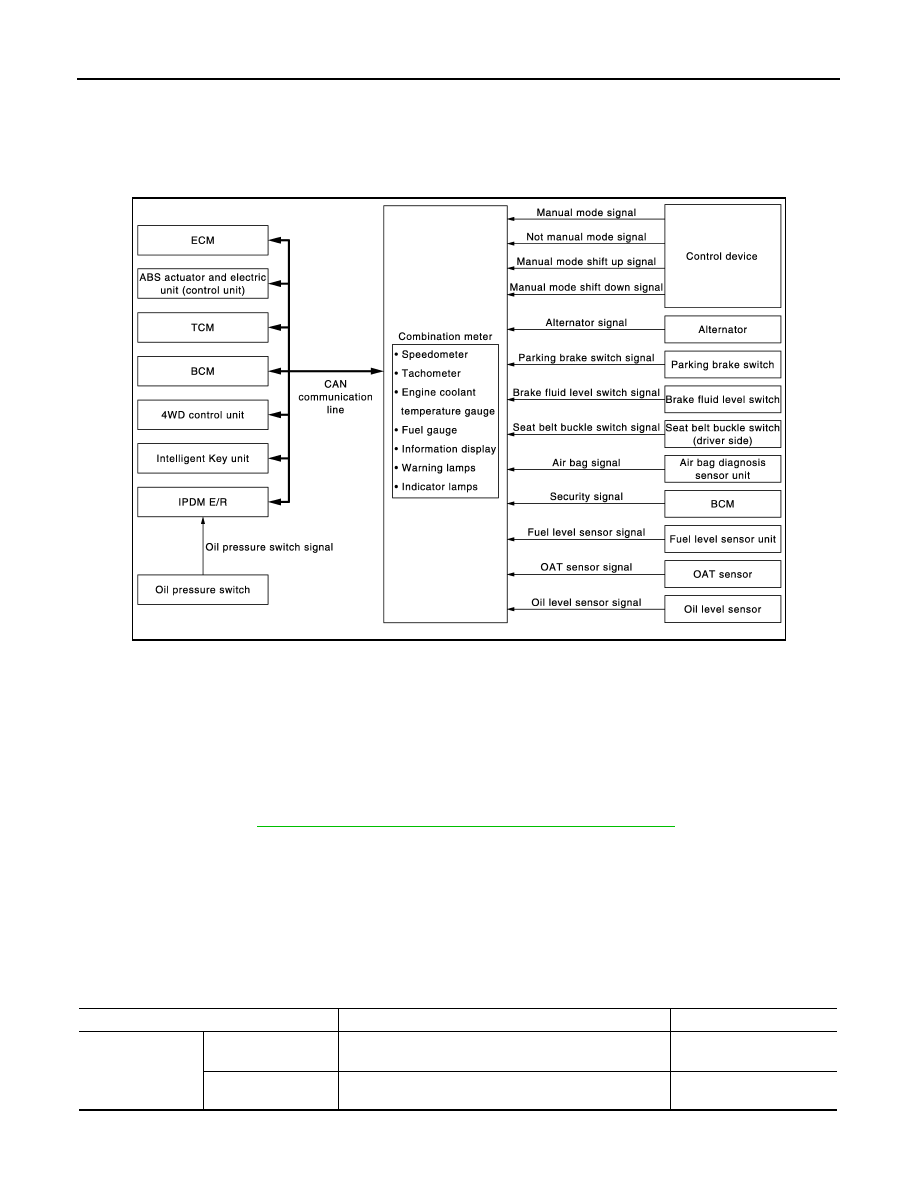
METER SYSTEM : System Diagram
INFOID:0000000000892244
METER SYSTEM : System Description
INFOID:0000000000892245
COMBINATION METER
• The combination meter receives the information required to control the operation of each gauge, indicator/
warning lamp, and information display via CAN communication from each unit, each switch, and sensor.
• The combination meter incorporates a trip computer that displays messages on the information display
according to the information received from various units.
• The combination meter incorporates a buzzer function that sounds an audible alarm with the integrated
buzzer device. Refer to
WCS-4, "WARNING CHIME SYSTEM : System Description"
for further details.
• The combination meter integrates the meter circuit check function and the segment check function that
checks the information display operation.
IPDM E/R
• IPDM E/R reads the ON/OFF signals of the oil pressure switch and transmits the oil pressure switch signal to
the combination meter via BCM with CAN communication.
• IPDM E/R is equipped with the diagnosis function. It can perform the operation check of oil pressure warning
lamp with the auto active test and the diagnosis with CONSULT-III.
METER CONTROL FUNCTION LIST
JSNIA0288GB
System
Description
Signal source
Meter
Speedometer
Receives vehicle speed signal and indicates vehicle
speed.
ABS actuator and electric
unit (control unit)
Tachometer
Receives engine speed signal and indicates engine
speed.
ECM

MWI
METER SYSTEM
MWI-5
< FUNCTION DIAGNOSIS >
C
D
E
F
G
H
I
J
K
L
M
B
A
O
P
Warning lamp
Oil pressure warning
lamp
Receives oil pressure warning lamp signal and illumi-
nates warning lamp.
IPDM E/R
Information display
Fuel gauge
Receives fuel level sensor signal and indicates fuel level.
Fuel level sensor unit
Engine coolant tem-
perature gauge
Receives engine coolant temperature signal and indi-
cates coolant temperature.
ECM
Maintenance
The remaining distance from the set distance is displayed
for 5 seconds after the ignition switch is turned ON.
ABS actuator and electric
unit (control unit)
Oil level
The oil level is displayed according to the oil level sensor
signal for 5 seconds after the maintenance display.
Oil level sensor
Possible driving dis-
tance
Calculates possible driving distance based on received
fuel consumption monitor signal, vehicle speed signals
and fuel level sensor signal and displays it.
ECM
ABS actuator and electric
unit (control unit)
Fuel level sensor unit
Average fuel con-
sumption
Calculates average fuel consumption in a reset-to-reset
interval based on received vehicle speed signals and fuel
consumption monitor signal and displays it.
ECM
ABS actuator and electric
unit (control unit)
Average vehicle
speed
Calculates average vehicle speed in a reset-to-reset in-
terval based on received vehicle speed signals and dis-
plays it.
ABS actuator and electric
unit (control unit)
Travel time
Displays accumulated key switch ON time from reset to
reset.
—
Odo/trip meter
Calculates accumulated travel distance based on re-
ceived vehicle speed signals and displays it.
ABS actuator and electric
unit (control unit)
Ambient air tempera-
ture
Corrects ambient temperature value based on received
OAT sensor signals and displays it.
OAT sensor
Clock
Time is displayed.
—
System
Description
Signal source
Нет комментариевНе стесняйтесь поделиться с нами вашим ценным мнением.
Текст