Nissan Qashqai (2007-2010). Manual — part 892
HA-138
< ON-VEHICLE REPAIR >
[MANUAL AIR CONDITIONER (HR/MR)]
REFRIGERATION SYSTEM
ON-VEHICLE REPAIR
REFRIGERATION SYSTEM
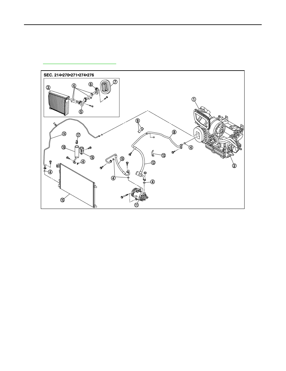
Exploded View
INFOID:0000000001098161
HA-171, "Refrigerant Connection"
Inspection After Installation
INFOID:0000000001098162
SETTING OF SERVICE TOOLS AND EQUIPMENT
Discharging Refrigerant
WARNING:
Avoid breathing A/C refrigerant and lubricant vapor or mist. Exposure may irritate eyes, nose and
throat. Remove HFC-134a (R-134a) from A/C system using certified service equipment meeting
requirements of SAE J-2210 [HFC-134a (R-134a) recycling equipment] or J-2209 [HFC-134a (R-134a)
recovery equipment]. If accidental system discharge occurs, ventilate work area before resuming ser-
vice. Additional health and safety information may be obtained from refrigerant and lubricant manu-
facturers.
1.
Heater & blower unit assembly
2.
Heater & cooling unit assembly
3.
Evaporator
4.
O-ring
5.
Low pressure pipe 1 and high pres-
sure pipe 2 assembly
6.
Expansion valve
7.
Heater sealing
8.
Low pressure flexible hose and pipe
2
9.
Low pressure pipe 2 fixing clamp as-
sembly
10. High pressure flexible hose
11.
Compressor
12. Low pressure flexible hose
13. Low & high pipe bracket support
14. High pressure pipe 1
15. Condenser assembly
16. Liquid tank fixing bracket
17. Refrigerant pressure sensor
18. Liquid tank
E1KIA0037GB
REFRIGERATION SYSTEM
HA-139
< ON-VEHICLE REPAIR >
[MANUAL AIR CONDITIONER (HR/MR)]
C
D
E
F
G
H
J
K
L
M
A
B
HA
N
O
P
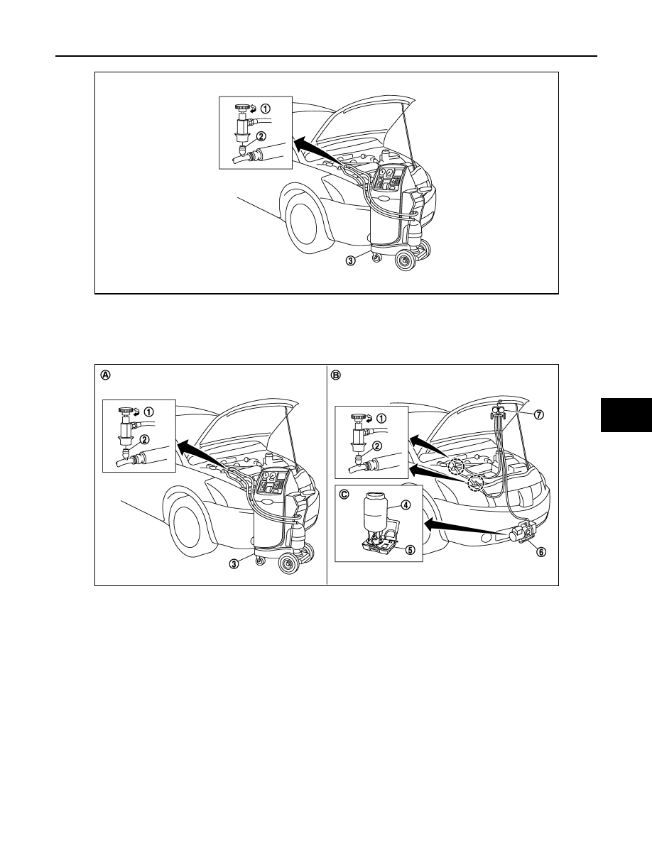
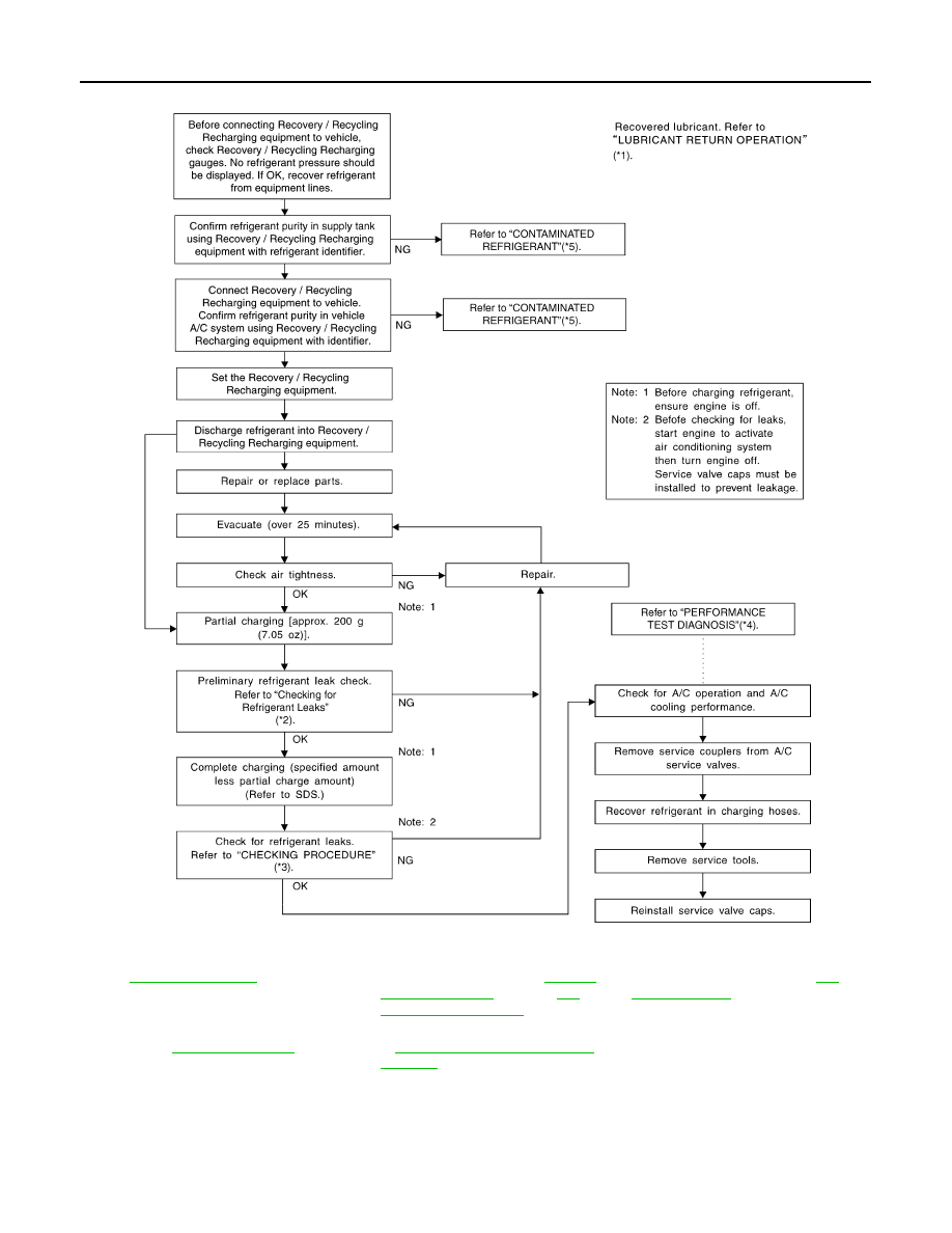
Evacuating System and Charging Refrigerant
1.
Shut-off valve
2.
A/C service valve
3.
Recovery/Recycling/Recharging
equipment
JSIIA0238ZZ
1.
Shut-off valve
2.
A/C service valve
3.
Recovery/Recycling/Recharging
equipment
4.
Refrigerant container (HFC-134a)
5.
Weight scale (J-39650)
6.
Vacuum pump (J-39649)
7.
Manifold gauge set (J-39183)
A.
Preferred (best) method
B.
Alternative method
C.
For charging
JSIIA0239ZZ
HA-140
< ON-VEHICLE REPAIR >
[MANUAL AIR CONDITIONER (HR/MR)]
REFRIGERATION SYSTEM
*1
*2
“REFRIGERANT LEAKS” in
*3
“CHECKING PROCEDURE” in
*4
“PERFORMANCE TEST DIAGNO-
SIS” in
*5
“CONTAMINATED REFRIGERANT”
in
HA-170, "Working with HFC-134a
SJIA1275E
COMPRESSOR
HA-141
< ON-VEHICLE REPAIR >
[MANUAL AIR CONDITIONER (HR/MR)]
C
D
E
F
G
H
J
K
L
M
A
B
HA
N
O
P
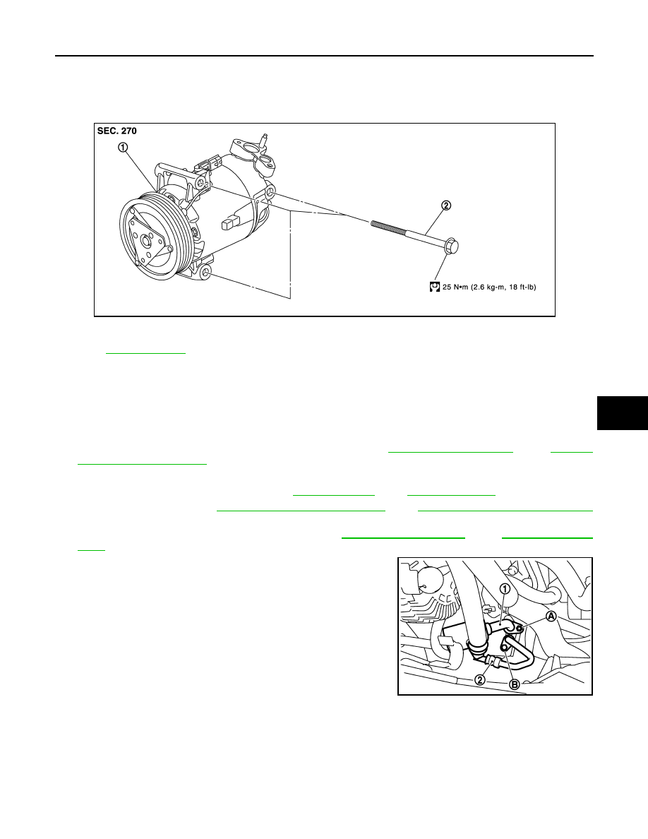
COMPRESSOR
Exploded View
INFOID:0000000001098163
Removal and Installation
INFOID:0000000001098164
REMOVAL
1.
Use a refrigerant collecting equipment (for HFC-134a) to discharge the refrigerant.
2.
Remove engine cover ornament.
3.
Remove air intake hoses (RH) and air duct (LH). Refer to
(MR).
4.
Remove engine undercover, using power tools.
5.
Drain engine coolant from radiator. Refer to
(MR).
6.
Remove drive belt. Refer to
EM-16, "Removal and Installation"
EM-134, "Removal and Installation"
(MR).
7.
Remove lower radiator hose from engine. Refer to
(MR).
8.
Remove mounting nuts (A) from low-pressure flexible hose (1)
and mounting bolt (B) from high-pressure flexible hose (2).
9.
Remove low-pressure flexible hose and high-pressure flexible
hose from compressor.
CAUTION:
Cap or wrap the joint of compressor, low-pressure flexible
hose and high-pressure flexible hose with suitable material
such as vinyl tape to avoid the entry of air.
10. Disconnect harness connector from compressor.
1.
Compressor
2.
Bolt
Refer to
E1KIA0046GB
E1KIA0067ZZ
Нет комментариевНе стесняйтесь поделиться с нами вашим ценным мнением.
Текст