Nissan Qashqai (2007-2010). Manual — part 51
EM-152
< ON-VEHICLE REPAIR >
[MR20DE]
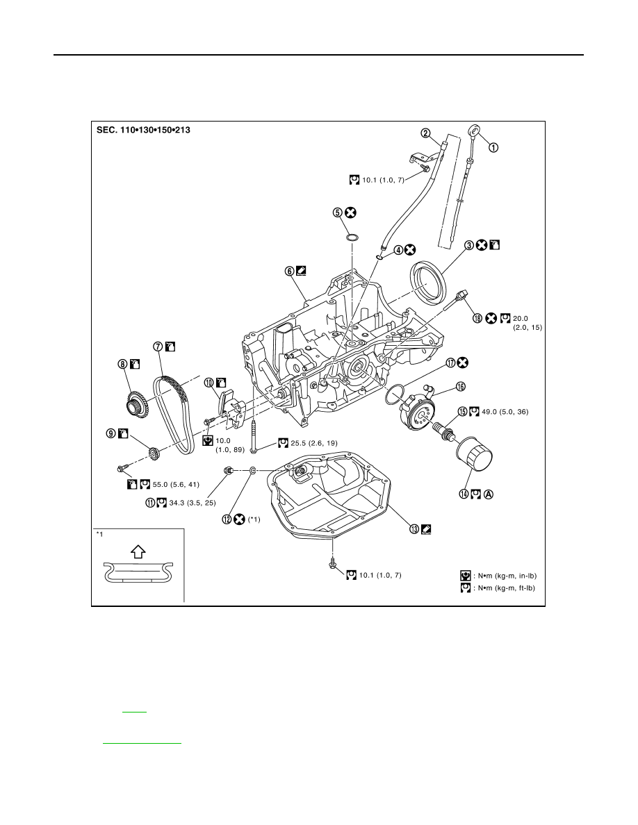
OIL PAN (LOWER)
OIL PAN (LOWER)
Exploded View
INFOID:0000000000893937
Removal and Installation
INFOID:0000000000893938
1.
Oil level gauge
2.
Oil level gauge guide
3.
Rear oil seal
4.
O-ring
5.
O-ring
6.
Oil pan (upper)
7.
Balancer unit timing chain
8.
Crankshaft sprocket
9.
Balancer unit sprocket
10. Balancer unit timing chain tensioner
11.
Drain plug
12. Drain plug washer
13. Oil pan (lower)
14. Oil filter
15. Connector bolt
16. Oil cooler
17. O-ring
18. Oil level sensor
A.
: Oil pan side
Refer to
for symbols in the figure.
PBIC5120J
OIL PAN (LOWER)
EM-153
< ON-VEHICLE REPAIR >
[MR20DE]
C
D
E
F
G
H
I
J
K
L
M
A
EM
N
P
O
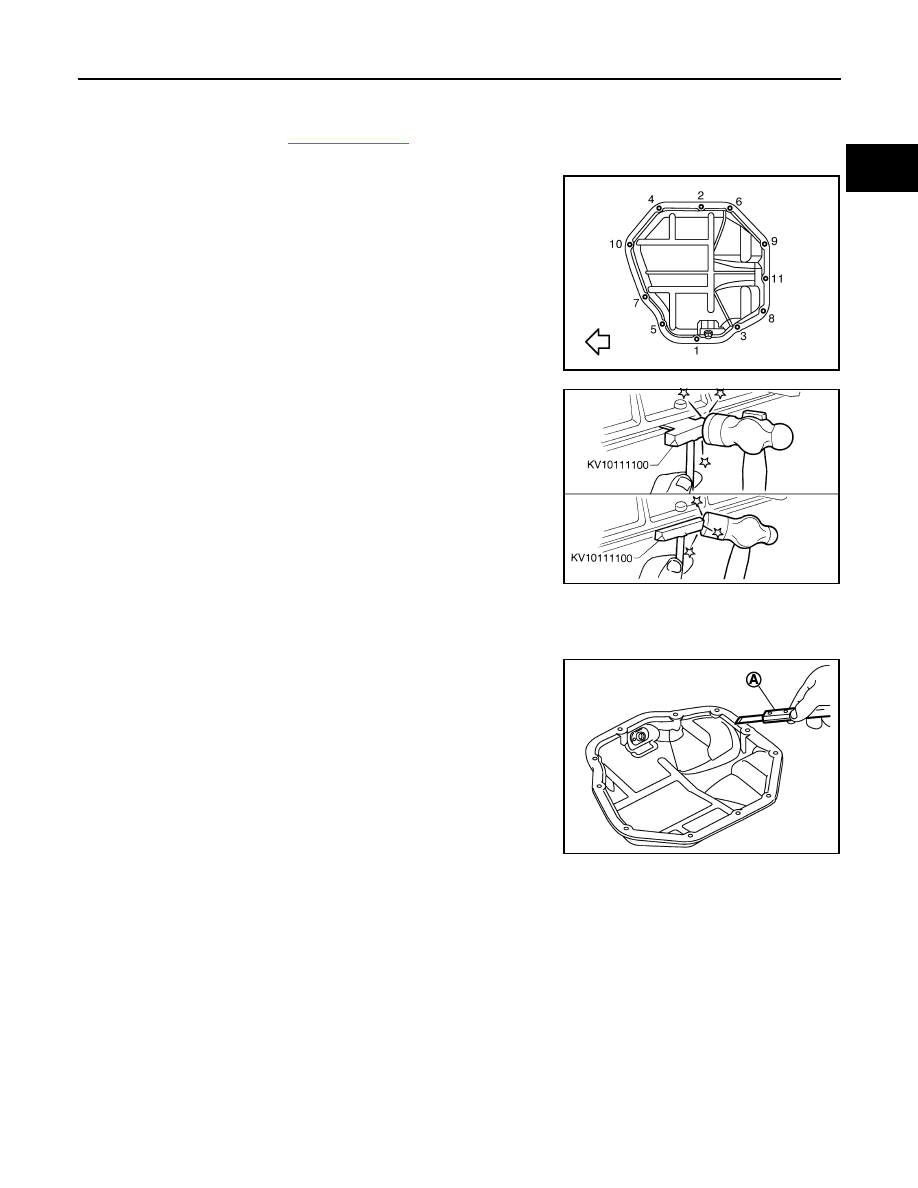
REMOVAL
1.
Remove engine undercover.
2.
Drain engine oil. Refer to
.
3.
Remove oil pan (lower) with the following procedure:
a.
Loosen mounting bolts in reverse order as shown in the figure.
b.
Insert seal cutter (SST) between oil pan (upper) and oil pan
(lower).
CAUTION:
Be careful not to damage the mating surface.
INSTALLATION
Note the following, and install in the reverse order of removal.
1.
Install oil pan (lower) with the following procedure:
a.
Use a scraper (A) to remove old liquid gasket from mating sur-
faces.
• Also remove old liquid gasket from mating surface of oil pan
(upper).
• Remove old liquid gasket from the bolt holes and threads.
: Engine front
PBIC3946E
SEM365EA
PBIC3953E
EM-154
< ON-VEHICLE REPAIR >
[MR20DE]
OIL PAN (LOWER)
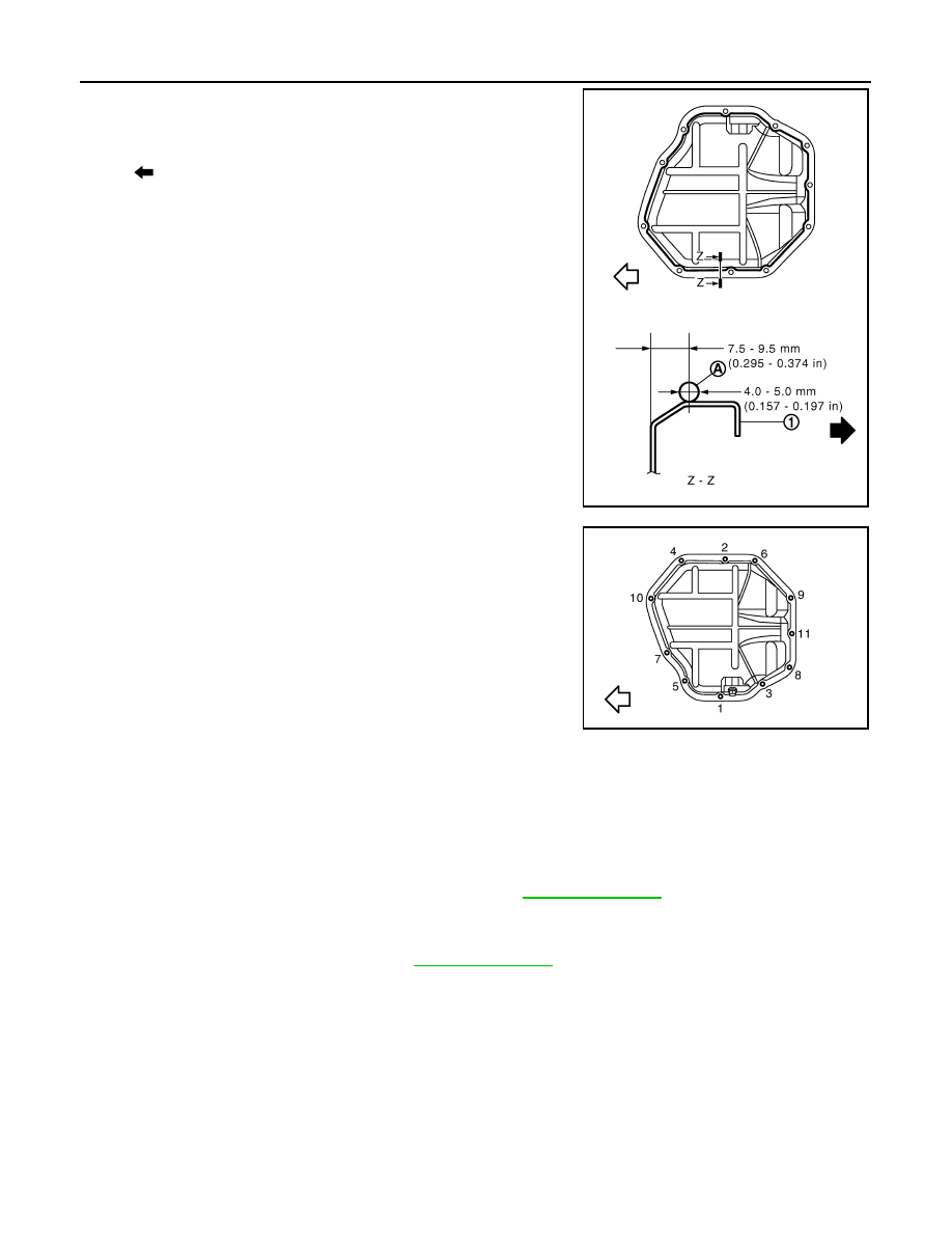
b.
Apply a continuous bead of liquid gasket (A) with a tube presser
(commercial service tool) as shown in the figure.
Use Genuine Liquid Gasket or equivalent.
c.
Tighten bolts in numerical order as shown in the figure.
Inspection
INFOID:0000000000893939
INSPECTION AFTER REMOVAL
Clean oil strainer portion [part of the oil pan (upper)] if any object attached.
INSPECTION AFTER INSTALLATION
1.
Check the engine oil level and adjust engine oil. Refer to
.
2.
Start engine, and check there is no leak of engine oil.
3.
Stop engine and wait for 10 minutes.
4.
Check the engine oil level again. Refer to
1
: Oil pan (lower)
: Engine outside
JPBIA0289ZZ
: Engine front
PBIC3946E
FUEL INJECTOR AND FUEL TUBE
EM-155
< ON-VEHICLE REPAIR >
[MR20DE]
C
D
E
F
G
H
I
J
K
L
M
A
EM
N
P
O
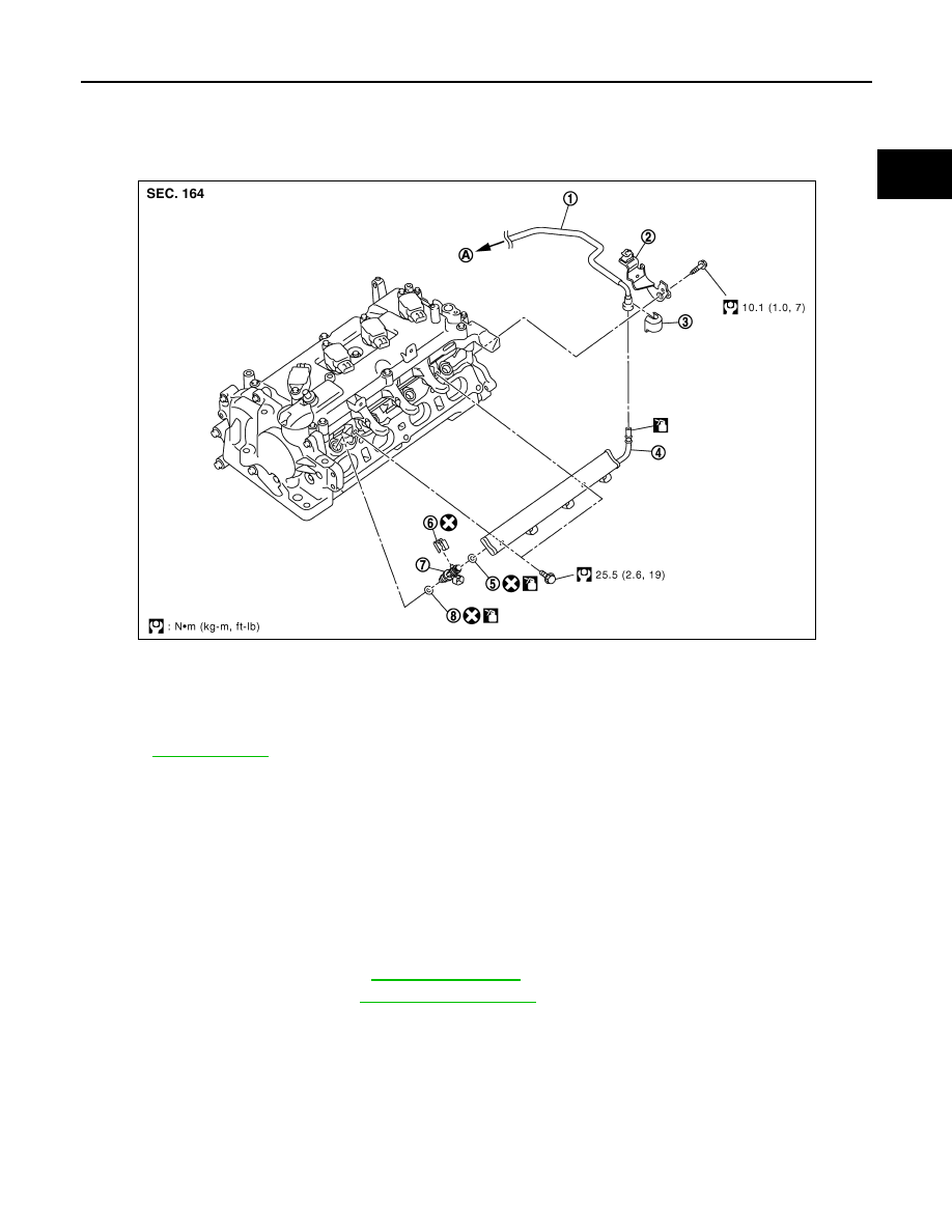
FUEL INJECTOR AND FUEL TUBE
Exploded View
INFOID:0000000000893940
CAUTION:
Never remove or disassemble parts unless instructed in the figure.
Removal and Installation
INFOID:0000000000893941
WARNING:
• Put a “CAUTION: FLAMMABLE” sign in the workshop.
• Be sure to work in a well ventilated area and furnish workshop with a CO
2
fire extinguisher.
• Never smoke while servicing fuel system. Keep open flames and sparks away from the work area.
REMOVAL
1.
Release the fuel pressure. Refer to
.
2.
Remove intake manifold. Refer to
1.
Fuel feed tube
2.
Bracket
3.
Quick connector cap
4.
Fuel tube
5.
O-ring (black)
6.
Clip
7.
Injector
8.
O-ring (green)
A.
To centralized under-floor piping
Refer to
for symbols in the figure.
PBIC3537J
Нет комментариевНе стесняйтесь поделиться с нами вашим ценным мнением.
Текст