Nissan Qashqai (2007-2010). Manual — part 627
DRIVE PINION
DLN-81
< DISASSEMBLY AND ASSEMBLY >
[TRANSFER: TY30A]
C
E
F
G
H
I
J
K
L
M
A
B
DLN
N
O
P
CAUTION:
Check that the drive pinion bearing preload is within the standard.
2.
Assemble the ring gear shaft assembly to the transfer case.
3.
Install adapter case. Refer to
4.
Rotate the companion flange at least 20 times to check for smooth operation of the bearing.
5.
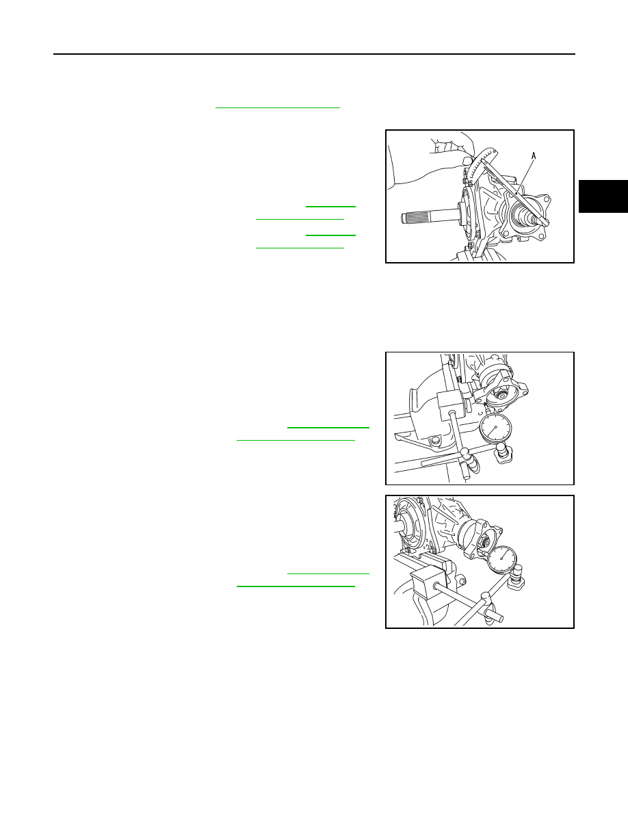
Measure the total preload with a preload gauge (A) (SST:
ST3127S000).
CAUTION:
• Each rotational part should rotate smoothly with the spec-
ified gear oil.
• Disassemble the transfer assembly to check and adjust each part if outside the standard. Mea-
sure it with the adapter case oil seals removed when measuring total preload after disassembly.
Then install adapter case oil seals.
COMPANION FLANGE RUNOUT
1.
Fit a dial indicator onto the companion flange face (inner side of
the propeller shaft bolt holes).
2.
Rotate the companion flange to check for runout.
3.
Fit a test indicator to the inner side of the companion flange
(socket diameter).
4.
Rotate the companion flange to check for runout.
5.
Follow the procedure below to adjust if runout value is outside
the repair limit.
CAUTION:
Replace collapsible spacer to check and adjust each part
when companion flange is adjusted or replaced.
a.
Check for runout while changing the phase between companion flange and drive pinion in 90
°
steps. Then
search for the minimum point.
b.
Replace companion flange if runout value is still outside the limit after the phase has been changed.
c.
Adjust assembly status of the drive pinion bearings and drive pinion, or replace drive pinion bearings if
runout is outside the standard after the companion flange is replaced.
ADJUSTING SHIM SELECTION
Measuring Point
Standard
Total preload
All oil seals are installed
: Refer to
.
Without adapter case oil seal
: Refer to
.
SDIA3073J
Limit
Companion flange runout
: Refer to
.
SDIA3074J
Limit
Companion flange runout
: Refer to
.
SDIA3075J
DLN-82
< DISASSEMBLY AND ASSEMBLY >
[TRANSFER: TY30A]
DRIVE PINION
Ring Gear Adjusting Shim (Adapter Case Side)
1.
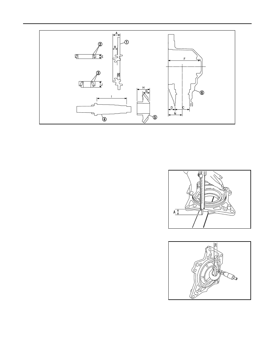
Measure the dimensions of each measuring point with the following procedure:
Dimension “A” measurement
• Measure dimension from transfer case mounting surface of
adapter case to adapter case edge surface with a pair of ver-
nier calipers and straightedge. Refer to “Measuring point”.
Dimension “B” measurement
• Measure dimension from ring gear adjusting shim mounting
surface of adapter case to adapter case edge surface with a
micrometer. Refer to “Measuring point”.
Dimension “C” measurement
1.
Adapter case
2.
Ring gear shaft bearing
(Adapter case side)
3.
Ring gear shaft bearing
(Transfer case side)
4.
Ring gear shaft
5.
Ring gear
6.
Transfer case
JSDIA0256ZZ
SDIA3105J
SDIA3114J
DRIVE PINION
DLN-83
< DISASSEMBLY AND ASSEMBLY >
[TRANSFER: TY30A]
C
E
F
G
H
I
J
K
L
M
A
B
DLN
N
O
P
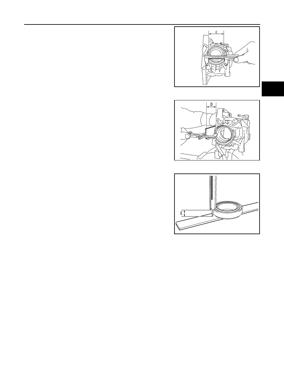
• Measure the diameter of drive pinion bearing (rear side)
mounting area of transfer case with a pair of vernier calipers.
Refer to “Measuring point”.
CAUTION:
Never damage transfer case.
Dimension “D” measurement
• Measure dimension from adapter case mounting surface of
transfer case to drive pinion bearing (rear side) mounting sur-
face with a pair of vernier calipers and straightedge. Refer to
“Measuring point”.
CAUTION:
• Never damage transfer case.
• Consider the thickness of a straightedge.
Dimension “E” measurement
• Measure dimension from outer race edge surface of ring gear
shaft bearing (adapter case side) to inner race edge surface
with a pair of vernier calipers. Refer to “Measuring point”.
2.
Calculate dimensions “M” and “N” by the formula below.
3.
Convert the dimensions “E”, “M” and “N” according to the standards below.
SDIA3107J
SDIA3108J
SDIA3109J
Dimension “M” = “A” – “B”
Dimension “N” = “C”
×
0.5 mm (0.020 in) + “D”
“E”
: Actual value regarding 20.00 mm (0.7874 in) as 0 in increments of 0.01 mm (0.0004 in).
“M”
: Actual value regarding 13.90 mm (0.5472 in) as 0 in increments of 0.01 mm (0.0004 in).
“N”
: Actual value regarding 55.00 mm (2.1654 in) as 0 in increments of 0.01 mm (0.0004 in).
DLN-84
< DISASSEMBLY AND ASSEMBLY >
[TRANSFER: TY30A]
DRIVE PINION
4.
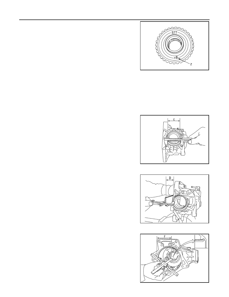
Check dimension “Z” (machining difference) on the ring gear
back surface.
NOTE:
Dimension “Z” indicates difference between optimum engage-
ment and the standard dimensions in increments of 0.01 mm
(0.0004 in) written on the ring gear back surface.
5.
Calculate the thickness of the ring gear adjusting shim (adapter
case side) “T
1
” by the formula below.
6.
Select ring gear adjusting shim (adapter case side).
CAUTION:
• Only one adjusting shim can be selected.
• Select the closest one, favoring thicker over thinner when necessary if no adjusting shim with
the calculated value is available.
Ring Gear Adjusting Shim (Transfer Case Side)
1.
Measure the dimensions of each measuring point with the following procedure:
Dimension “C” measurement
• Measure the diameter of drive pinion bearing (rear side)
mounting area of transfer case with a pair of vernier calipers.
Refer to “Measuring point”.
CAUTION:
Never damage transfer case.
Dimension “D” measurement
• Measure dimension from adapter case mounting surface of
transfer case to drive pinion bearing (rear side) mounting sur-
face with a pair of vernier calipers and straightedge. Refer to
“Measuring point”.
CAUTION:
• Never damage transfer case.
• Consider the thickness of a straightedge.
Dimension “F” measurement
• Measure dimension from adapter case mounting surface of
transfer case to ring gear adjusting shim mounting surface
with a depth gauge. Refer to “Measuring point”.
CAUTION:
Never damage transfer case.
“T
1
” = (“M” + “N” – “E” – “Z”)
×
0.01 mm (0.0004 in)
+ 1.40 mm (0.0551 in)
SDIA3129J
SDIA3107J
SDIA3108J
SDIA3110J
Нет комментариевНе стесняйтесь поделиться с нами вашим ценным мнением.
Текст