Nissan Qashqai (2007-2010). Manual — part 238

P0134 HO2S1
EC-471
< COMPONENT DIAGNOSIS >
[HR16DE (WITHOUT EURO-OBD)]
C
D
E
F
G
H
I
J
K
L
M
A
EC
N
P
O
YES
>> GO TO 2.
NO
>> GO TO 3.
2.
PERFORM DTC CONFIRMATION PROCEDURE-I
With CONSULT-III
1.
Start engine and warm it up to normal operating temperature.
2.
Select "MANU TRIG" in "DATA MONITOR" mode with CONSULT-III, and select "HO2S1 (B1)".
3.
Hold engine speed at 2,000 rpm under no load.
4.
Make sure that the indications do not remain in the range between 0.2V to 0.4V.
Is the inspection result normal?
YES
>> INSPECTION END.
NO
>> Go to
3.
PERFORM COMPONENT FUNCTION CHECK
Without CONSULT-III
1.
Start engine and warm it up to normal operating temperature.
2.
Set volmeter probes between ECM harness connector and ground.
Is the inspection result normal?
YES
>> INSPECTION END.
NO
>> Go to
Diagnosis Procedure
INFOID:0000000001096816
1.
CHECK GROUND CONNECTION
1.
Turn ignition switch OFF.
2.
Check ground connection E21. Refer to Ground Inspection in
.
Is the inspection result normal?
YES
>> GO TO 2.
NO
>> Repair or replace ground connection.
2.
CHECK HO2S1 GROUND CIRCUIT FOR OPEN AND SHORT
1.
Disconnect heated oxygen sensor 1 harness connector.
2.
Disconnect ECM harness connector.
3.
Check harness continuity between HO2S1 harness connector and ECM harness connector.
4.
Also check harness for short to ground and short to power.
Is inspection result normal?
YES
>> GO TO 3.
NG
>> Repair open circuit or short to ground or short to power in harness or connectors.
3.
CHECK HO2S1 INPUT SIGNAL CIRCUIT FOR OPEN AND SHORT
1.
Check harness continuity between HO2S1 harness connector and ECM harness connector 49.
ECM
Ground
Condition
Voltage
Connector
Terminal
F8
49
(HO2S1 signal)
Ground
Engine speed held at 2,000
rpm constant under no load.
• The voltage dose not remain in the range of 0.2 to 0.4.
HO2S1
ECM
Continuity
Connector
Terminal
Connector
Terminal
F30
1
F8
56
Existed
EC-472
< COMPONENT DIAGNOSIS >
[HR16DE (WITHOUT EURO-OBD)]
P0134 HO2S1
2.
Check harness continuity between ECM harness connector 49 or HO2S1 harness connector and ground.
3.
Also check harness for short to power.
Is inspection result normal?
YES
>> GO TO 4.
NO
>> Repair open circuit or short to ground or short to power in harness or connectors.
4.
CHECK HEATED OXYGEN SENSOR 1
EC-473, "Component Inspection"
Is inspection result normal?
YES
>> GO TO 5.
NO
>> Replace heated oxygen sensor 1.
5.
CHECK INTERMITTENT INCIDENT
GI-39, "Intermittent Incident"
>> INSPECTION END
Component Inspection
INFOID:0000000001096817
1.
INSPECTION START
Do you have CONSULT-III?
Do you have CONSULT-III?
YES
>> GO TO 2.
NO
>> GO TO 3.
2.
CHECK HEATED OXYGEN SENSOR 1
With CONSULT-III
1.
Start engine and warm it up to normal operating temperature.
2.
Set “POST TRIGGER” to 100% in “DATA MONITOR” mode with CONSULT-III.
3.
Select “HO2S1 (B1)” and “HO2S1 MNTR (B1)”.
4.
Hold engine speed at 2,000 rpm under no load during the following steps.
5.
Touch “RECORD” on CONSULT-III screen.
6.
Check the following.
-
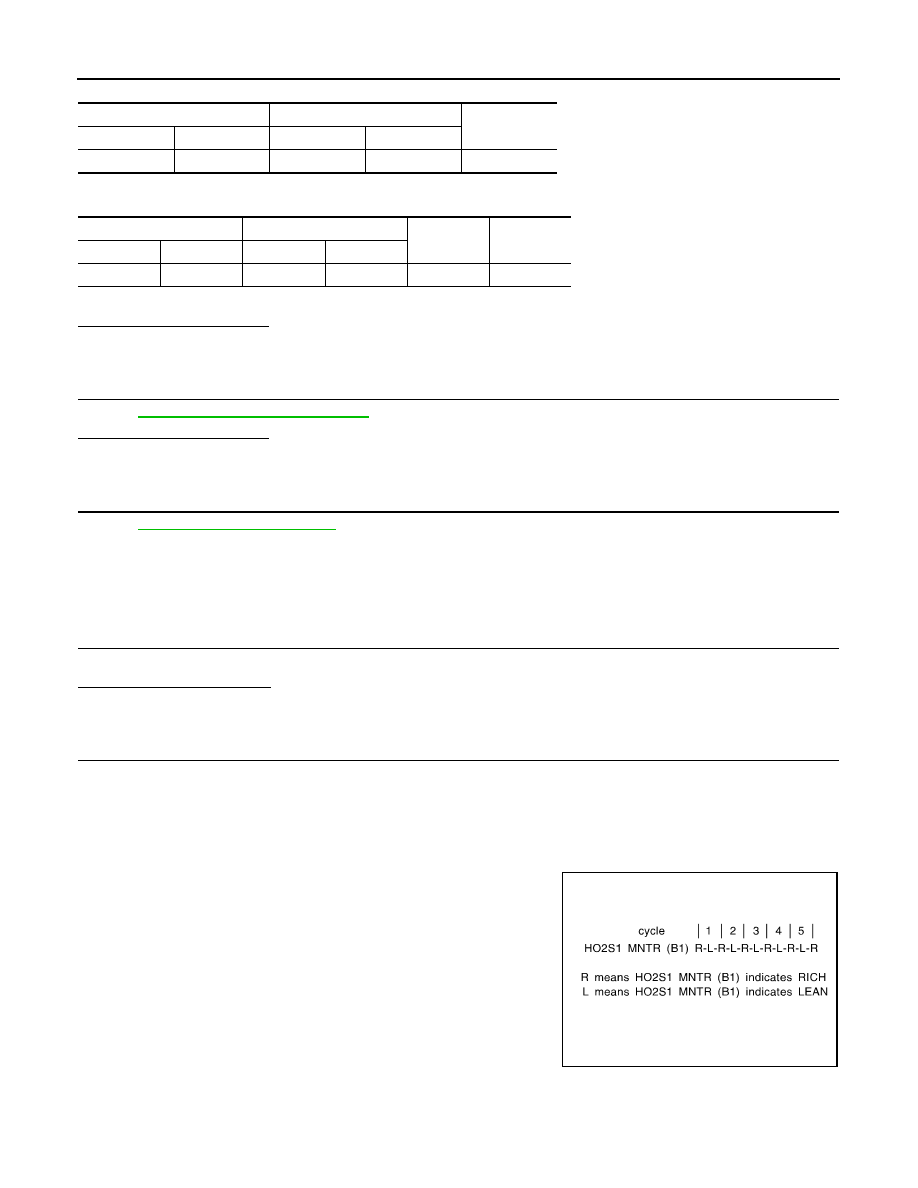
“HO2S1 MNTR (B1)” in “DATA MONITOR” mode changes from
“RICH” to “LEAN” to “RICH” more than 5 times in 10 seconds.
5 times (cycles) are counted as shown in the figure.
-
“HO2S1 (B1)” voltage goes above 0.6V at least once.
-
“HO2S1 (B1)” voltage goes below 0.3V at least once.
-
“HO2S1 (B1)” voltage never exceeds 1.0V.
HO2S1
ECM
Continuity
Connector
Terminal
Connector
Terminal
F30
4
F8
49
Existed
HO2S1
ECM
Ground
Continuity
Connector
Terminal
Connector
Terminal
F30
4
F8
49
Ground
Not existed
SEF217YA
P0134 HO2S1
EC-473
< COMPONENT DIAGNOSIS >
[HR16DE (WITHOUT EURO-OBD)]
C
D
E
F
G
H
I
J
K
L
M
A
EC
N
P
O
CAUTION:
•
Discard any heated oxygen sensor which has been dropped from a height of more than 0.5 m
(19.7 in) onto a hard surface such as a concrete floor; use a new one.
•
Before installing new oxygen sensor, clean exhaust system threads using Oxygen Sensor
Thread Cleaner tool and approved anti-seize lubricant.
Is the inspection result normal?
YES
>> INSPECTION END
NO
>> GO TO 4.
3.
CHECK HEATED OXYGEN SENSOR 1
Without CONSULT-III
1.
Start engine and warm it up to normal operating temperature.
2.
Check the voltage between ECM harness connector and ground under the following condition.
CAUTION:
• Discard any heated oxygen sensor which has been dropped from a height of more than 0.5 m (19.7
in) onto a hard surface such as a concrete floor; use a new one.
• Before installing new oxygen sensor, clean exhaust system threads using Oxygen Sensor Thread
Cleaner tool and approved anti-seize lubricant.
Is the inspection result normal?
YES
>> INSPECTION END
NO
>> GO TO 4.
4.
REPLACE HEATED OXYGEN SENSOR 1
Replace heated oxygen sensor 1.
CAUTION:
• Discard any heated oxygen sensor which has been dropped from a height of more than 0.5 m (19.7
in) onto a hard surface such as a concrete floor; use a new one.
• Before installing new oxygen sensor, clean exhaust system threads using Oxygen Sensor Thread
Cleaner tool and approved anti-seize lubricant.
>> INSPECTION END
JMBIA0352ZZ
ECM
ground
Condition
Voltage
Connector
Terminal
F8
49
(HO2S1 signal)
Ground
Engine speed held at 2,000
rpm constant under no load.
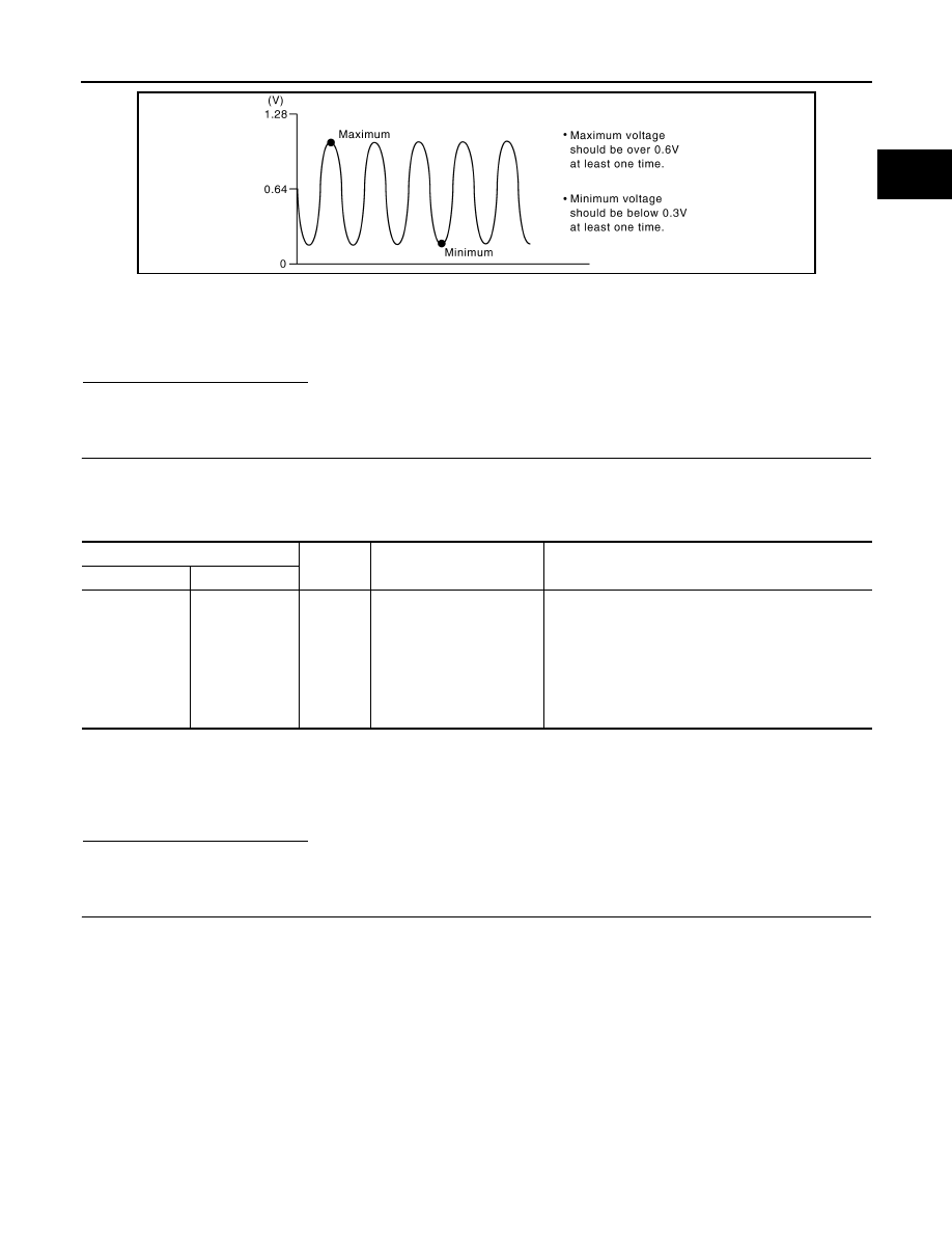
• The voltage fluctuates between 0 to 0.3V and 0.6 to
1.0V more than 5 times within 10 seconds.
• The maximum voltage is over 0.6V at least 1 time.
• The minimum voltage is below 0.3V at least 1 time.
• The voltage never exceeds 1.0V.
1 time: 0 - 0.3V
→
0.6 - 1.0V
→
0 - 0.3V
2 times: 0 - 0.3V
→
0.6 - 1.0V
→
0 - 0.3V
→
0.6 - 1.0V
→
0 - 0.3V
EC-474
< COMPONENT DIAGNOSIS >
[HR16DE (WITHOUT EURO-OBD)]
P0138 HO2S2
P0138 HO2S2
Description
INFOID:0000000001096822
The heated oxygen sensor 2, after three way catalyst (manifold),
monitors the oxygen level in the exhaust gas on each bank.
Even if switching characteristics of the heated oxygen sensor 1 are
shifted, the air-fuel ratio is controlled to stoichiometric, by the signal
from the heated oxygen sensor 2.
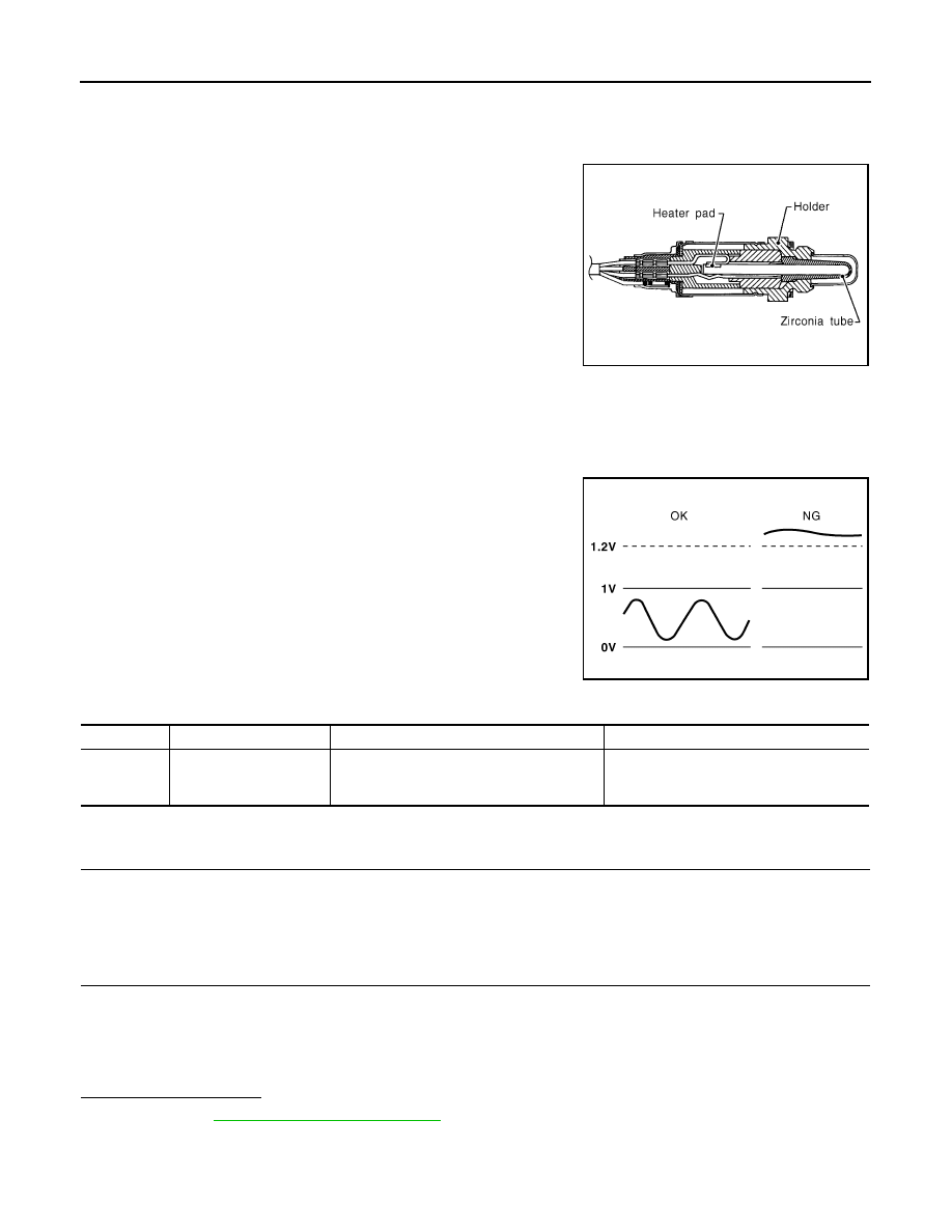
This sensor is made of ceramic zirconia. The zirconia generates volt-
age from approximately 1V in richer conditions to 0V in leaner condi-
tions.
Under normal conditions the heated oxygen sensor 2 is not used for
engine control operation.
DTC Logic
INFOID:0000000001096823
DTC DETECTION LOGIC
The heated oxygen sensor 2 has a much longer switching time between rich and lean than the heated oxygen
sensor 1. The oxygen storage capacity of the three way catalyst (manifold) causes the longer switching time.
To judge the malfunctions of heated oxygen sensor 2, ECM monitors
whether the voltage is unusually high during the various driving con-
dition such as fuel-cut.
DTC CONFIRMATION PROCEDURE
1.
PRECONDITIONING
If DTC Confirmation Procedure has been previously conducted, always turn ignition switch OFF and wait at
least 10 seconds before conducting the next test.
>> GO TO 2.
2.
PERFORM DTC CONFIRMATION PROCEDURE
1.
Start engine and warm it up to the normal operating temperature.
2.
Turn ignition switch OFF and wait at least 10 seconds.
3.
Start engine and keep the engine speed between 3,500 and 4,000 rpm for at least 1 minute under no load.
4.
Let engine idle for 2 minutes.
5.
Check 1st trip DTC.
Is 1st trip DTC detected?
YES
>> Go to
NO
>> INSPECTION END
Diagnosis Procedure
INFOID:0000000001096824
SEF327R
PBIB1848E
DTC No.
Trouble diagnosis name
DTC detecting condition
Possible cause
P0138
Heated oxygen sensor 2
circuit high voltage
An excessively high voltage from the sensor
is sent to ECM.
• Harness or connectors
(The sensor circuit is open or shorted)
• Heated oxygen sensor 2
Нет комментариевНе стесняйтесь поделиться с нами вашим ценным мнением.
Текст