Nissan Qashqai (2007-2010). Manual — part 237

P0132 HO2S1
EC-467
< COMPONENT DIAGNOSIS >
[HR16DE (WITHOUT EURO-OBD)]
C
D
E
F
G
H
I
J
K
L
M
A
EC
N
P
O
2.
PERFORM DTC CONFIRMATION PROCEDURE
1.
Start engine and warm it up to normal operating temperature.
2.
Turn ignition switch OFF and wait at least 10 seconds.
3.
Restart engine and let it idle for 2 minutes.
4.
Check 1st trip DTC.
Is 1st trip DTC is detected?
YES
>> Go to
EC-1091, "Diagnosis Procedure"
NO
>> INSPECTION END
Diagnosis Procedure
INFOID:0000000001096808
1.
CHECK GROUND CONNECTION
1.
Turn ignition switch OFF.
2.
Check ground connection E21. Refer to Ground Inspection in
.
Is the inspection result normal?
YES
>> GO TO 2.
NO
>> Repair or replace ground connection.
2.
RETIGHTEN HEATED OXYGEN SENSOR 1
Loosen and retighten heated oxygen sensor 1.
>> GO TO 3.
3.
CHECK HO2S1 GROUND CIRCUIT FOR OPEN AND SHORT
1.
Disconnect heated oxygen sensor 1 harness connector.
2.
Disconnect ECM harness connector.
3.
Check harness continuity between HO2S1 harness connector and ECM harness connector.
4.
Also check harness for short to ground and short to power.
Is the inspection result normal?
YES
>> GO TO 4.
NO
>> Repair open circuit or short to ground or short to power in harness or connectors.
4.
CHECK HO2S1 INPUT SIGNAL CIRCUIT FOR OPEN AND SHORT
1.
Check harness continuity between HO2S1 harness connector and ECM harness connector.
2.
Check harness continuity between HO2S1 harness connector or ECM harness connector.
3.
Also check harness for short to power.
Is the inspection result normal?
YES
>> GO TO 5.
Tightening torque: 50 N·m (5.1 kg-m, 37 ft-lb)
HO2S1
ECM
Continuity
Connector
Terminal
Connector
Terminal
F30
1
F8
56
existed
HO2S1
ECM
Continuity
Connector
Terminal
Connector
Terminal
F30
4
F8
49
existed
HO2S1
ECM
Ground
Continuity
Connector
Terminal
Connector
Terminal
F30
4
F8
49
Ground
Not existed
EC-468
< COMPONENT DIAGNOSIS >
[HR16DE (WITHOUT EURO-OBD)]
P0132 HO2S1
NO
>> Repair open circuit or short to ground or short to power in harness or connectors.
5.
CHECK HO2S1 CONNECTOR FOR WATER
Check heated oxygen sensor 1 connector for water.
Is the inspection result normal?
YES
>> GO TO 6.
NO
>> Repair or replace harness or connectors.
6.
CHECK HEATED OXYGEN SENSOR 1
EC-469, "Component Inspection"
Is the inspection result normal?
YES
>> GO TO 7.
NO
>> Replace heated oxygen sensor 1.
7.
CHECK INTERMITTENT INCIDENT
GI-39, "Intermittent Incident"
>> INSPECTION END
Component Inspection
INFOID:0000000001096809
1.
INSPECTION START
Do you have CONSULT-III?
Do you have CONSULT-III?
YES
>> GO TO 2.
NO
>> GO TO 3.
2.
CHECK HEATED OXYGEN SENSOR 1
With CONSULT-III
1.
Start engine and warm it up to normal operating temperature.
2.
Set “POST TRIGGER” to 100% in “DATA MONITOR” mode with CONSULT-III.
3.
Select “HO2S1 (B1)” and “HO2S1 MNTR (B1)”.
4.
Hold engine speed at 2,000 rpm under no load during the following steps.
5.
Touch “RECORD” on CONSULT-III screen.
6.
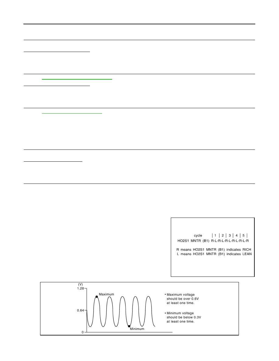
Check the following.
-
“HO2S1 MNTR (B1)” in “DATA MONITOR” mode changes from
“RICH” to “LEAN” to “RICH” more than 5 times in 10 seconds.
5 times (cycles) are counted as shown in the figure.
-
“HO2S1 (B1)” voltage goes above 0.6V at least once.
-
“HO2S1 (B1)” voltage goes below 0.3V at least once.
-
“HO2S1 (B1)” voltage never exceeds 1.0V.
CAUTION:
SEF217YA
JMBIA0352ZZ

P0132 HO2S1
EC-469
< COMPONENT DIAGNOSIS >
[HR16DE (WITHOUT EURO-OBD)]
C
D
E
F
G
H
I
J
K
L
M
A
EC
N
P
O
•
Discard any heated oxygen sensor which has been dropped from a height of more than 0.5 m
(19.7 in) onto a hard surface such as a concrete floor; use a new one.
•
Before installing new oxygen sensor, clean exhaust system threads using Oxygen Sensor
Thread Cleaner tool and approved anti-seize lubricant.
Is the inspection result normal?
YES
>> INSPECTION END
NO
>> GO TO 3.
3.
CHECK HEATED OXYGEN SENSOR 1
Without CONSULT-III
1.
Start engine and warm it up to normal operating temperature.
2.
Check the voltage between ECM harness connector and ground under the following condition.
CAUTION:
• Discard any heated oxygen sensor which has been dropped from a height of more than 0.5 m (19.7
in) onto a hard surface such as a concrete floor; use a new one.
• Before installing new oxygen sensor, clean exhaust system threads using Oxygen Sensor Thread
Cleaner tool and approved anti-seize lubricant.
Is the inspection result normal?
YES
>> INSPECTION END
NO
>> GO TO 4
4.
REPLACE HEATED OXYGEN SENSOR 1
Replace heated oxygen sensor 1.
CAUTION:
• Discard any heated oxygen sensor which has been dropped from a height of more than 0.5 m (19.7
in) onto a hard surface such as a concrete floor; use a new one.
• Before installing new oxygen sensor, clean exhaust system threads using Oxygen Sensor Thread
Cleaner tool and approved anti-seize lubricant.
>> INSPECTION END
ECM
ground
Condition
Voltage
Connector
Terminal
F8
49
(HO2S1 signal)
Ground
Engine speed held at 2,000
rpm constant under no load.
• The voltage fluctuates between 0 to 0.3V and 0.6 to
1.0V more than 5 times within 10 seconds.
• The maximum voltage is over 0.6V at least 1 time.
• The minimum voltage is below 0.3V at least 1 time.
• The voltage never exceeds 1.0V.
1 time: 0 - 0.3V
→
0.6 - 1.0V
→
0 - 0.3V
2 times: 0 - 0.3V
→
0.6 - 1.0V
→
0 - 0.3V
→
0.6 - 1.0V
→
0 - 0.3V
EC-470
< COMPONENT DIAGNOSIS >
[HR16DE (WITHOUT EURO-OBD)]
P0134 HO2S1
P0134 HO2S1
Description
INFOID:0000000001096814
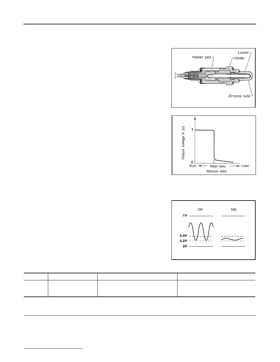
The heated oxygen sensor 1 is placed into the exhaust manifold. It
detects the amount of oxygen in the exhaust gas compared to the
outside air. The heated oxygen sensor 1 has a closed-end tube
made of ceramic zirconia. The zirconia generates voltage from
approximately 1V in richer conditions to 0V in leaner conditions. The
heated oxygen sensor 1 signal is sent to the ECM. The ECM adjusts
the injection pulse duration to achieve the ideal air-fuel ratio. The
ideal air-fuel ratio occurs near the radical change from 1V to 0V.
DTC Logic
INFOID:0000000001102039
DTC DETECTION LOGIC
Under the condition in which the heated oxygen sensor 1 signal is
not input, the ECM circuits will read a continuous approximately
0.3V. Therefore, for this diagnosis, the time that output voltage is
within 200 to 400 mV range is monitored, and the diagnosis checks
that this time is not inordinately long.
DTC CONFIRMATION PROCEDURE
1.
PRECONDITIONING
If DTC Confirmation Procedure has been previously conducted, always turn ignition switch OFF and wait at
least 10 seconds before conducting the next test.
TESTING CONDITION:
Always perform at a temperature above -10
°
C (14
°
F).
Before performing the following procedure, confirm that battery voltage is more than 11V at idle.
Do you have CONSULT-III?
SEF463R
SEF288D
SEF237U
DTC No.
Trouble diagnosis name
DTC detecting condition
Possible cause
P0134
0134
Heated oxygen sensor 1
circuit no activity detected
The voltage from the sensor is constantly ap-
prox. 0.3V.
• Harness or connectors
(The sensor circuit is open or shorted.)
• Heated oxygen sensor 1
Нет комментариевНе стесняйтесь поделиться с нами вашим ценным мнением.
Текст