Nissan Qashqai (2007-2010). Manual — part 1962

AV-106
< COMPONENT DIAGNOSIS >
[AUDIO WITH NAVIGATION]
RGB SYNCHRONIZING SIGNAL CIRCUIT
RGB SYNCHRONIZING SIGNAL CIRCUIT
Description
INFOID:0000000000947096
Transmits the RGB synchronizing signal to the display unit so as to synchronize the RGB image displayed
with NAVI control unit.
Diagnosis Procedure
INFOID:0000000000947097
1.
CHECK CONTINUITY RGB SYNCHRONIZING SIGNAL CIRCUIT
1.
Turn ignition switch OFF.
2.
Disconnect display unit connector and NAVI control unit connector.
3.
Check continuity between display unit harness connector terminal 7 and NAVI control unit harness con-
nector terminal 48.
4.
Check continuity between display unit harness connector terminal 7 and ground.
Is inspection result OK?
YES
>> GO TO 2.
NO
>> Repair harness or connector.
2.
CHECK RGB SYNCHRONIZING SIGNAL
1.
Connect display unit connector and NAVI control unit connector.
2.
Turn ignition switch ON.
3.
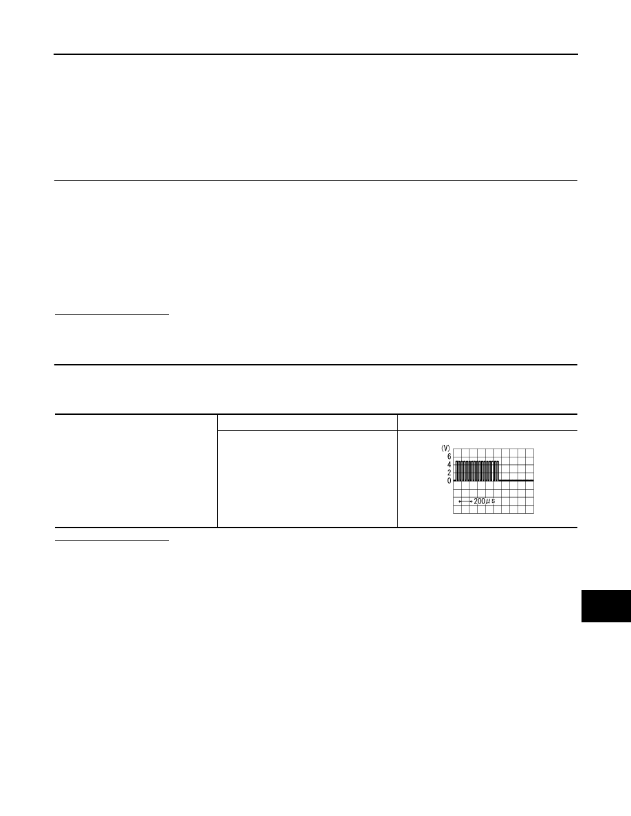
Check signal between display unit harness connector terminal 7 and ground.
Is inspection result OK?
YES
>> Replace display unit.
NO
>> Replace NAVI control unit.
7 - 48
: Continuity should exist.
7 - Ground
: Continuity should not exist.
7 - Ground
SKIB0825E
AV
RGB AREA (YS) SIGNAL CIRCUIT
AV-107
< COMPONENT DIAGNOSIS >
[AUDIO WITH NAVIGATION]
C
D
E
F
G
H
I
J
K
L
M
B
A
O
P
RGB AREA (YS) SIGNAL CIRCUIT
Description
INFOID:0000000000947098
Transmits the display area of RGB image displayed by NAVI control unit with RGB area (YS) signal to display
unit.
Diagnosis Procedure
INFOID:0000000000947099
1.
CHECK CONTINUITY RGB AREA (YS) SIGNAL CIRCUIT
1.
Turn ignition switch OFF.
2.
Disconnect display unit connector and NAVI control unit connector.
3.
Check continuity between display unit harness connector terminal 2 and NAVI control unit harness con-
nector terminal 50.
4.
Check continuity between display unit harness connector terminal 2 and ground.
Is inspection result OK?
YES
>> GO TO 2.
NO
>> Repair harness or connector.
2.
CHECK RGB SYNCHRONIZING SIGNAL
1.
Connect display unit connector and NAVI control unit connector.
2.
Turn ignition switch ON.
3.
Check signal between display unit harness connector terminal 2 and ground.
Is inspection result OK?
YES
>> Replace display unit.
NO
>> Replace NAVI control unit.
2 - 50
: Continuity should exist.
2 - Ground
: Continuity should not exist.
2 - Ground
At RGB image displayed
: Approx. 5 V
At rear view camera image displayed
PKIB4948J
AV-108
< COMPONENT DIAGNOSIS >
[AUDIO WITH NAVIGATION]
HORIZONTAL SYNCHRONIZING (HP) SIGNAL CIRCUIT
HORIZONTAL SYNCHRONIZING (HP) SIGNAL CIRCUIT
Description
INFOID:0000000000947100
In composite image (camera image), it transmits the vertical synchronizing (VP) signal and horizontal synchro-
nizing (HP) signal from display unit to NAVI control unit so as to synchronize the RGB images displayed with
NAVI control unit such as the image quality adjusting menu, etc.
Diagnosis Procedure
INFOID:0000000000947101
1.
CHECK CONTINUITY HORIZONTAL SYNCHRONIZING (HP) SIGNAL CIRCUIT
1.
Turn ignition switch OFF.
2.
Disconnect display unit connector and NAVI control unit connector.
3.
Check continuity between display unit harness connector terminal 4 and NAVI control unit harness con-
nector terminal 51.
4.
Check continuity between display unit harness connector terminal 4 and ground.
Is inspection result OK?
YES
>> GO TO 2.
NO
>> Repair harness or connector.
2.
CHECK HORIZONTAL SYNCHRONIZING (HP) SIGNAL
1.
Connect display unit connector and NAVI control unit connector.
2.
Turn ignition switch ON.
3.
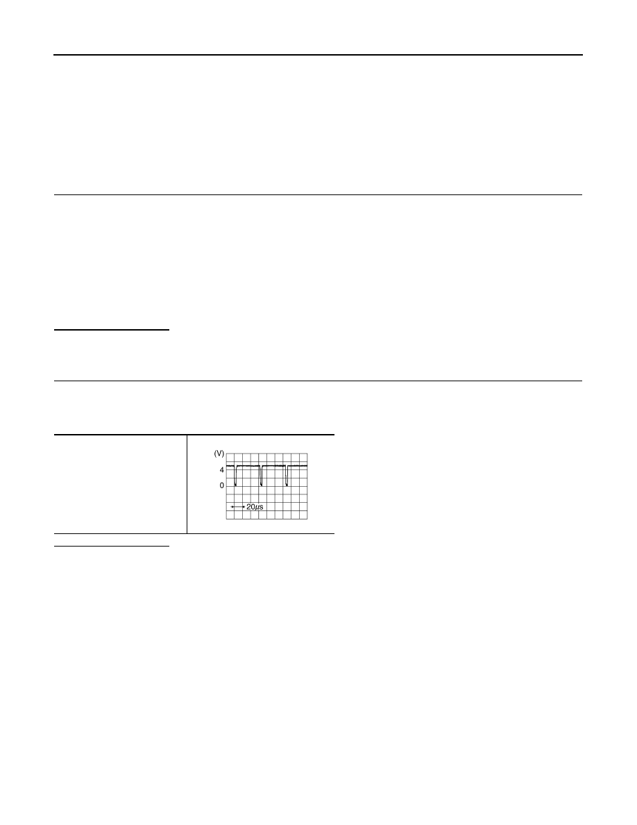
Check signal between display unit harness connector terminal 4 and ground.
Is inspection result OK?
YES
>> Replace NAVI control unit.
NO
>> Replace display unit.
4 - 51
: Continuity should exist.
4 - Ground
: Continuity should not exist.
4 - Ground
SKIB0825E

AV
VERTICAL SYNCHRONIZING (VP) SIGNAL CIRCUIT
AV-109
< COMPONENT DIAGNOSIS >
[AUDIO WITH NAVIGATION]
C
D
E
F
G
H
I
J
K
L
M
B
A
O
P
VERTICAL SYNCHRONIZING (VP) SIGNAL CIRCUIT
Description
INFOID:0000000000947102
In composite image (camera image), it is transmits the vertical synchronizing (VP) signal and horizontal syn-
chronizing (HP) signal from display unit to NAVI control unit so as to synchronize the RGB images displayed
with NAVI control unit such as the image quality adjusting menu, etc.
Diagnosis Procedure
INFOID:0000000000947103
1.
CHECK CONTINUITY VERTICAL SYNCHRONIZING (VP) SIGNAL CIRCUIT
1.
Turn ignition switch OFF.
2.
Disconnect display unit connector and NAVI control unit connector.
3.
Check continuity between display unit harness connector terminal 6 and NAVI control unit harness con-
nector terminal 52.
4.
Check continuity between display unit harness connector terminal 6 and ground.
Is inspection result OK?
YES
>> GO TO 2.
NO
>> Repair harness or connector.
2.
CHECK VERTICAL SYNCHRONIZING (VP) SIGNAL
1.
Connect display unit connector and NAVI control unit connector.
2.
Turn ignition switch ON.
3.
Check signal between display unit harness connector terminal 6 and ground.
Is inspection result OK?
YES
>> Replace NAVI control unit.
NO
>> Replace display unit.
6 - 52
: Continuity should exist.
6 - Ground
: Continuity should not exist.
6 - Ground
SKIB0823E
Нет комментариевНе стесняйтесь поделиться с нами вашим ценным мнением.
Текст