Nissan Qashqai (2007-2010). Manual — part 652

FAX-30
< ON-VEHICLE REPAIR >
[2WD]
FRONT DRIVE SHAFT
2.
Press support bearing onto housing.
3.
Install snap ring.
CAUTION:
Never reuse snap ring.
4.
Install dust shields.
CAUTION:
Never reuse dust shields.
Dynamic Damper
Secure dynamic damper with bands in the following specified posi-
tion when removing.
CAUTION:
Never reuse bands.
Wheel Side
For further details, refer to the installation procedure of “
” for the drive shaft boot.
MR20DE MODELS : Inspection
INFOID:0000000001070382
INSPECTION AFTER REMOVAL
• Move joint up/down, left/right, and in the axial directions. Check for motion that is not smooth and for signifi-
cant looseness.
• Check boot for cracks, damage, and leakage of grease.
• Disassemble drive shaft and exchange malfunctioning part if there
is a non-standard condition.
YAX007
YAX008
Standard
.
FAC0156D
SDIA1190J
FRONT DRIVE SHAFT
FAX-31
< ON-VEHICLE REPAIR >
[2WD]
C
E
F
G
H
I
J
K
L
M
A
B
FAX
N
O
P
INSPECTION AFTER DISASSEMBLY
Shaft
Check shaft for runout, cracks, or other damage. Replace if there are.
Dynamic Damper
Check damper for cracks or wear. Replace if necessary.
Joint Sub-Assembly (Wheel Side)
Check the following:
• Joint sub-assembly for rough rotation and excessive axial looseness
• The inside of the joint sub-assembly for entry of foreign material
• Joint sub-assembly for compression scars, cracks, and fractures inside of joint sub-assembly
Replace joint sub-assembly if there are any non-standard conditions of components.
Housing and Spider assembly (Transaxle Side)
Replace housing and spider assembly if there is scratching or wear of housing roller contact surface or spider
roller contact surface.
NOTE:
Housing and spider assembly are used in a set.
Support Bearing (Right Side)
Make sure wheel bearing rolls freely and is free from noise, cracks, pitting or wear. Replace support bearing if
there are any non-standard conditions.
Support Bearing Bracket (Right Side)
Check for bending, cracks, or damage. Replace support bearing bracket if there are any non-standard condi-
tions.
K9K MODELS
K9K MODELS : Exploded View
INFOID:0000000001070383
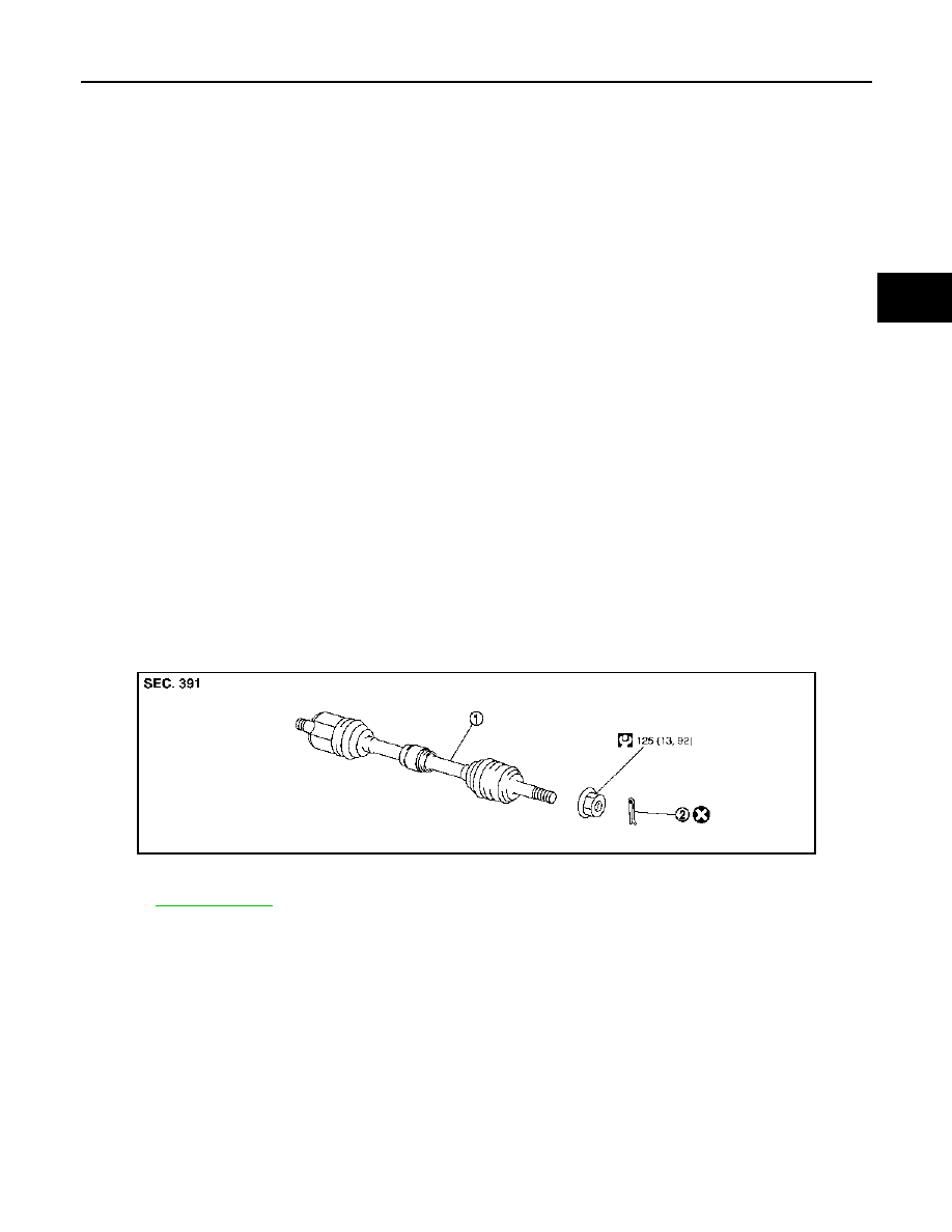
REMOVAL
Left side
PDIA1192J
1.
Drive shaft
2.
Cotter pin
Refer to
FAX-32
< ON-VEHICLE REPAIR >
[2WD]
FRONT DRIVE SHAFT
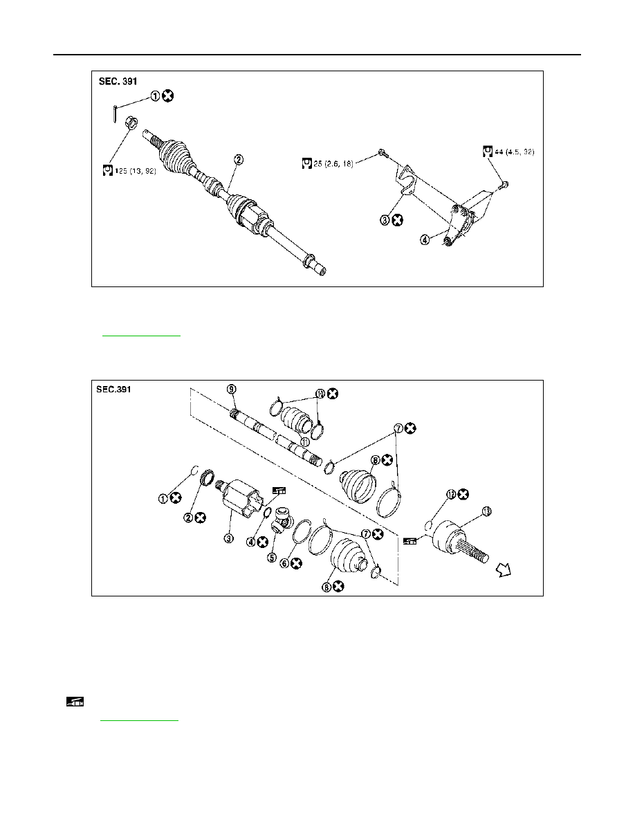
Right side
DISASSEMBLY
Left side
JPDIF0042GB
1.
Cotter pin
2.
Drive shaft
3.
Plate
4.
Support bearing bracket
Refer to
for symbols in the figure.
JPDIF0047ZZ
1.
Circular clip
2.
Dust shield
3.
Housing
4.
Snap ring
5.
Spider assembly
6.
Stopper ring
7.
Boot band
8.
Boot
9.
Shaft
10. Damper band
11. Dynamic damper
12. Circular clip
13. Joint sub-assembly
: Wheel side
: Fill NISSAN Genuine grease or equivalent.
for symbols not described on the above.
FRONT DRIVE SHAFT
FAX-33
< ON-VEHICLE REPAIR >
[2WD]
C
E
F
G
H
I
J
K
L
M
A
B
FAX
N
O
P
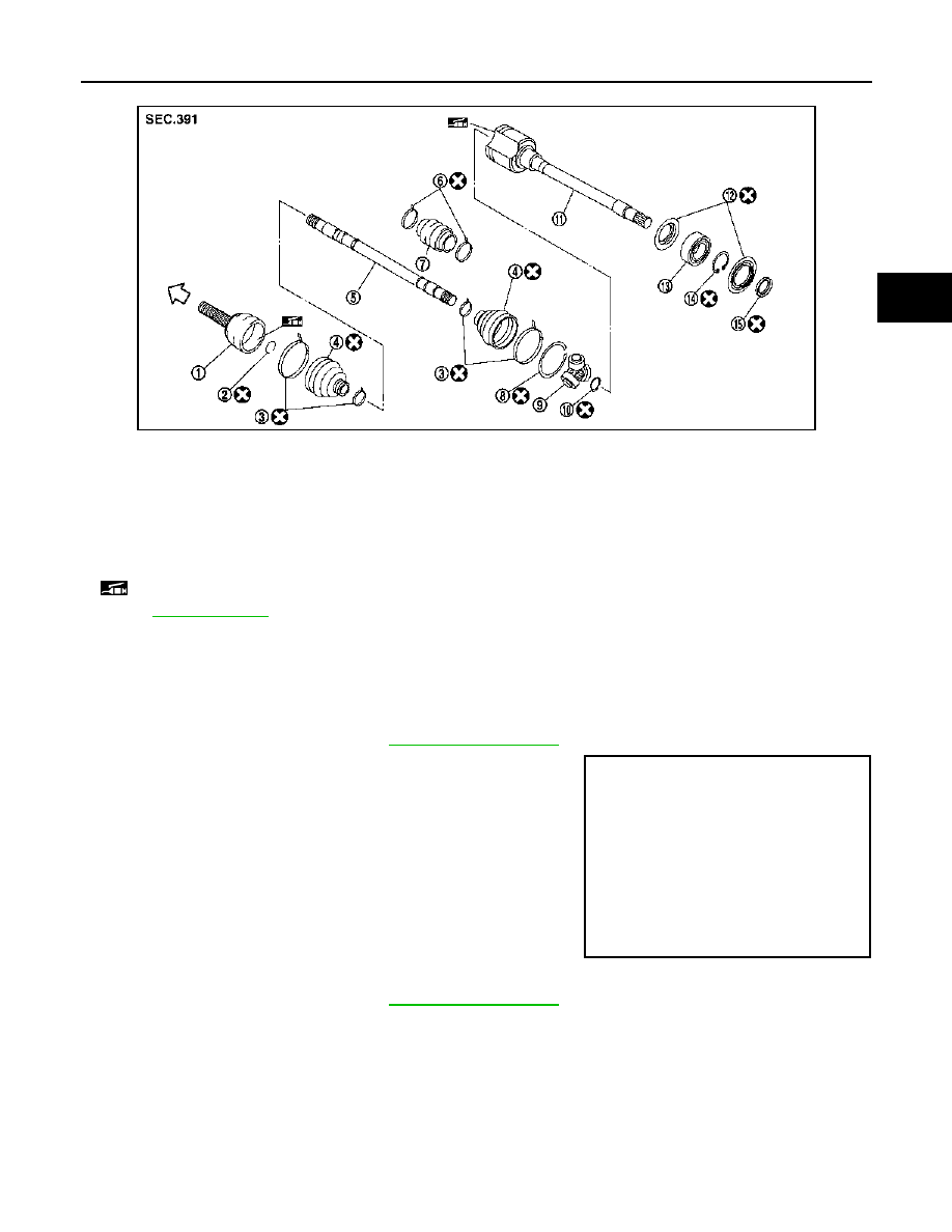
Right side
K9K MODELS : Removal and Installation
INFOID:0000000001070384
REMOVAL
Left Side
1.
Refer to the procedure from 1 to 11 in
2.
Remove drive shaft from transaxle assembly.
• Use the drive shaft attachment (A) (SST:KV40107500) and a
sliding hammer (B) while inserting tip of the drive shaft attach-
ment between housing and transaxle assembly.
CAUTION:
Never place drive shaft joint at an extreme angle when
removing drive shaft. Also be careful not to overextend
slide joint.
Right Side
1.
Refer to the procedure from 1 to 11 in
2.
Remove plate bolts and plate.
3.
If necessary, remove the support bearing bracket bolts and the support bearing bracket.
4.
Remove drive shaft from transaxle assembly.
• Use the drive shaft attachment (SST:KV40107500) and a sliding hammer while inserting tip of the drive
shaft attachment between housing and transaxle assembly.
CAUTION:
Never place drive shaft joint at an extreme angle when removing drive shaft. Also be careful not
to overextend slide joint.
JPDIF0045ZZ
1.
Joint sub-assembly
2.
Circular clip
3.
Boot band
4.
Boot
5.
Shaft
6.
Damper band
7.
Dynamic damper
8.
Stopper ring
9.
Spider assembly
10. Snap ring
11. Housing
12. Dust shield
13. Support bearing
14. Snap ring
15. Dust shield
: Wheel side
: Fill NISSAN Genuine grease or equivalent.
Refer to
for symbols not described on the above.
JPDIF0004ZZ
Нет комментариевНе стесняйтесь поделиться с нами вашим ценным мнением.
Текст