Nissan Qashqai (2007-2010). Manual — part 653

FAX-34
< ON-VEHICLE REPAIR >
[2WD]
FRONT DRIVE SHAFT
INSTALLATION
Left Side
Note the following, and install in the reverse order of removal.
• Place the protector (A) (SST:KV38107900) onto transaxle assem-
bly to prevent damage to the oil seal while inserting drive shaft.
Slide drive shaft sliding joint and tap with a hammer to install
securely.
CAUTION:
Make sure that circular clip is completely engaged.
Right Side
Note the following, and install in the reverse order of removal.
• Place the protector (A) (SST:KV38107900) onto transaxle assem-
bly to prevent damage to the oil seal while inserting drive shaft.
Slide drive shaft sliding joint and tap with a hammer to install
securely.
• When installing plate (1) to support bearing bracket (2), set plate
so that notch (A) becomes upper side. Temporarily tighten mount-
ing bolts in the order of (B), (C).
CAUTION:
Never reuse plate.
K9K MODELS : Disassembly and Assembly
INFOID:0000000001070385
DISASSEMBLY
Transaxle Assembly Side
1.
Fix shaft with a vise.
CAUTION:
Protect shaft using aluminum or copper plates when fixing with a vise.
2.
Remove boot bands, and then remove boot from housing.
3.
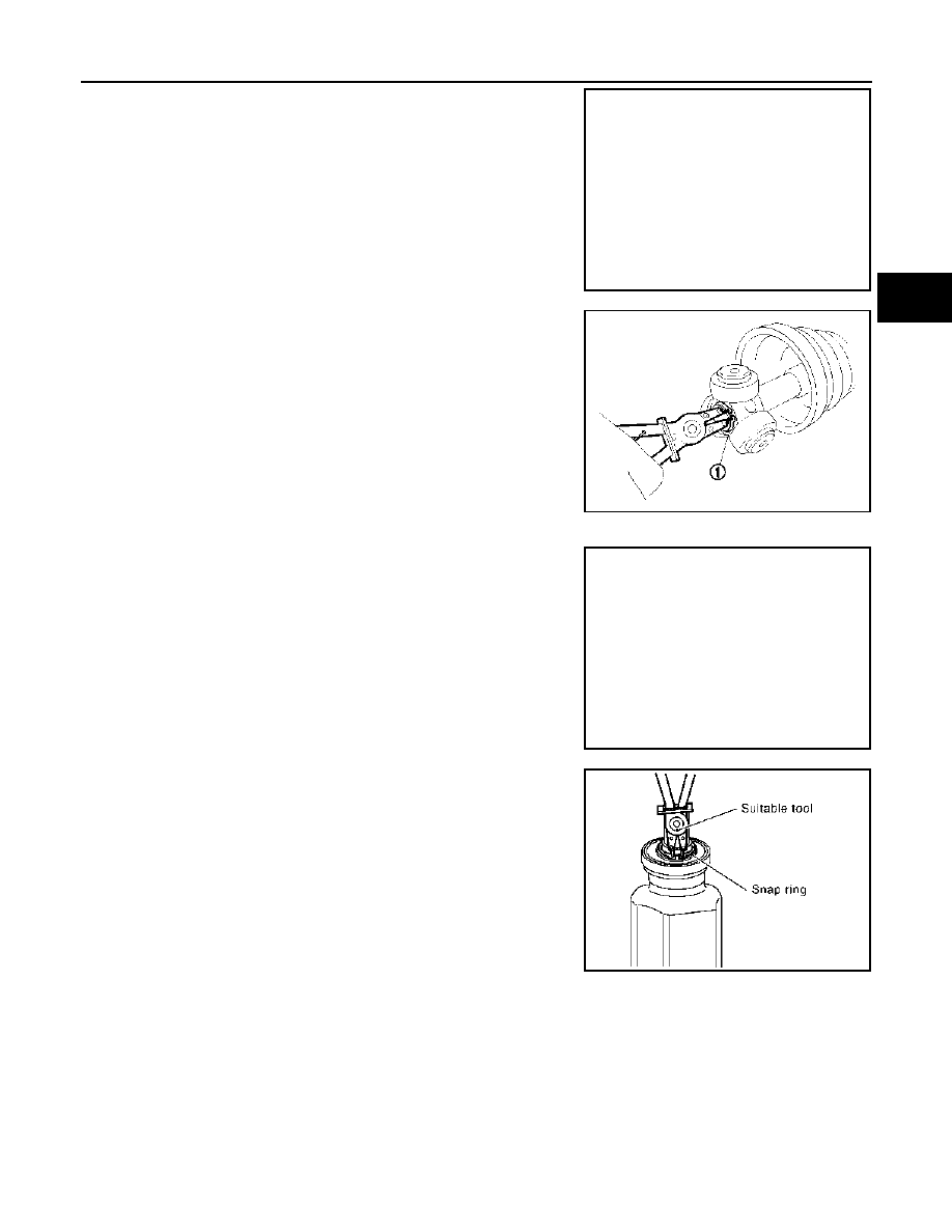
Remove stopper ring.
4.
Put matching marks on housing and shaft, and then pull out housing from shaft.
CAUTION:
Use paint or an equivalent for matching marks. Never scratch the surfaces.
JPDIF0023ZZ
JPDIF0049ZZ
PDIA1275J
FRONT DRIVE SHAFT
FAX-35
< ON-VEHICLE REPAIR >
[2WD]
C
E
F
G
H
I
J
K
L
M
A
B
FAX
N
O
P
5.
Put matching marks (A) on the spider assembly and shaft.
CAUTION:
Use paint or an equivalent for matching marks. Never
scratch the surfaces.
6.
Remove snap ring (1), and then remove spider assembly from
shaft.
7.
Remove boot from shaft.
8.
Remove circular clip from shaft (left side).
9.
Remove dust shield from housing.
10. Clean old grease on housing with paper towels.
Support Bearing
1.
Remove dust shield from housing.
2.
Remove snap ring.
JPDIF0006ZZ
JPDIF0014ZZ
YAX002
YAX003
FAX-36
< ON-VEHICLE REPAIR >
[2WD]
FRONT DRIVE SHAFT
3.
Press out support bearing from housing.
4.
Remove dust shield.
Dynamic Damper
Remove damper bands, then remove dynamic damper from shaft.
Wheel Side
1.
Fix shaft with a vise.
CAUTION:
Protect shaft using aluminum or copper plates when fixing with a vise.
2.
Remove boot bands, and then remove boot from joint sub-assembly.
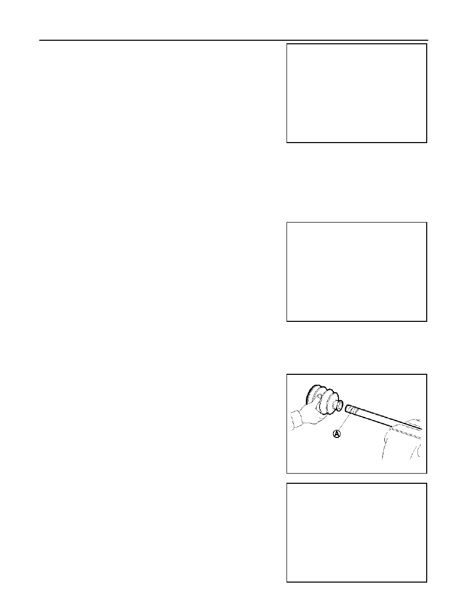
3.
Screw the drive shaft puller (A) 30 mm (1.18 in) or more into the
thread of joint sub-assembly, and pull joint sub-assembly with a
sliding hammer (B) from shaft.
CAUTION:
• If joint sub-assembly cannot be removed after five or
more unsuccessful attempts, replace shaft and joint sub
assembly as a set.
• Align sliding hammer and drive shaft and remove them by
pulling directory.
4.
Remove circular clip from shaft.
5.
Remove boot from shaft.
6.
Clean old grease on joint sub-assembly with paper towels while
rotating ball cage.
ASSEMBLY
Transaxle Assembly Side
1.
Wrap serration on shaft with tape (A) to protect boot from dam-
age. Install new boot and boot bands to shaft.
CAUTION:
Never reuse boot and boot band.
2.
Remove the tape wrapped around the serration on shaft.
3.
To install the spider assembly (1), align it with the matching
marks (A) on the shaft (2) during the removal, and direct the ser-
ration mounting surface (B) to the shaft.
YAX004
JPDIF0015ZZ
JPDIF0009ZZ
JPDIF0017ZZ
FRONT DRIVE SHAFT
FAX-37
< ON-VEHICLE REPAIR >
[2WD]
C
E
F
G
H
I
J
K
L
M
A
B
FAX
N
O
P
4.
Secure spider assembly onto shaft with snap ring (1).
CAUTION:
Never reuse snap ring.
5.
Apply the appropriate amount of grease to spider assembly and
sliding surface.
6.
Assemble the housing onto spider assembly, and apply the bal-
ance of the specified amount grease.
7.
Align matching marks put during the removal of housing.
8.
Install stopper ring.
CAUTION:
Never reuse stopper ring.
9.
Install boot securely into grooves (indicated by “*” marks) shown
in the figure.
CAUTION:
If grease adheres to the boot mounting surface (with “*”
mark) on shaft or housing, boot may be removed. Remove
all grease from the surface.
10. To prevent from deformation of the boot, adjust the boot installa-
tion length to the value shown below (L) by inserting the suitable
tool into the inside of boot from the large diameter side of boot
and discharging inside air.
CAUTION:
• If the boot installation length exceeds the standard, it may cause breakage in boot.
• Be careful not to touch the inside of the boot with the tip of tool.
11. Install new larger and smaller boot bands securely.
CAUTION:
Never reuse boot band.
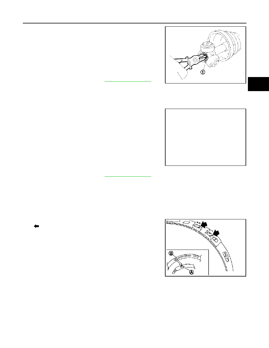
12. Put boot band in the groove on drive shaft boot. Then fit pawls
(
) into holes to temporary installation.
NOTE:
For the large diameter side, fit projection (A) and guide slit (B) at
first.
Standard
Grease amount
Standard
Boots installed
length (L)
JPDIF0014ZZ
JPDIF0032ZZ
SDIA3557E
Нет комментариевНе стесняйтесь поделиться с нами вашим ценным мнением.
Текст