Nissan Qashqai (2007-2010). Manual — part 39

EM-104
< DISASSEMBLY AND ASSEMBLY >
[HR16DE]
CYLINDER BLOCK
Measure the outer diameter of piston pin with a micrometer.
Connecting Rod Small End Clearance
(Connecting rod small end clearance) = (Connecting rod small end inner diameter) – (Piston pin outer diame-
ter)
• If the measured value is out of the standard, replace connecting rod assembly and/or piston and piston pin
assembly.
• If replacing connecting rod assembly, refer to "CONNECTING ROD BEARING OIL CLEARANCE" to select
connecting rod bearing.
CYLINDER BLOCK TOP SURFACE DISTORTION
• Using a scraper, remove gasket on the cylinder block surface, and also remove engine oil, scale, carbon, or
other contamination.
CAUTION:
Be careful not to allow gasket flakes to enter engine oil or engine coolant passages.
• Measure the distortion on the cylinder block upper face at some
different points in six directions with a straight edge and a feeler
gauge.
• If it exceeds the limit, replace cylinder block.
MAIN BEARING HOUSING INNER DIAMETER
• Install main bearing cap without main bearings installed, and tighten main bearing cap bolts to the specified
EM-94, "Disassembly and Assembly"
• Measure the position shown in the figure [5 mm (0.196 in) rear-
ward from main bearing housing front side end surface) in the 2
directions as shown in the figure. The smaller one is the measured
value.
• If out of the standard, replace cylinder block and main bearing
caps as an assembly.
NOTE:
These components cannot be replaced as a single unit, because they were processed together.
PISTON TO CYLINDER BORE CLEARANCE
Standard
: Refer to
.
PBIC0117E
Standard
: Refer to
.
Limit
: Refer to
.
PBIC0121E
1
: Cylinder block
2
: Main bearing cap
: Engine front
Standard
: Refer to
.
PBIC3879E
CYLINDER BLOCK
EM-105
< DISASSEMBLY AND ASSEMBLY >
[HR16DE]
C
D
E
F
G
H
I
J
K
L
M
A
EM
N
P
O
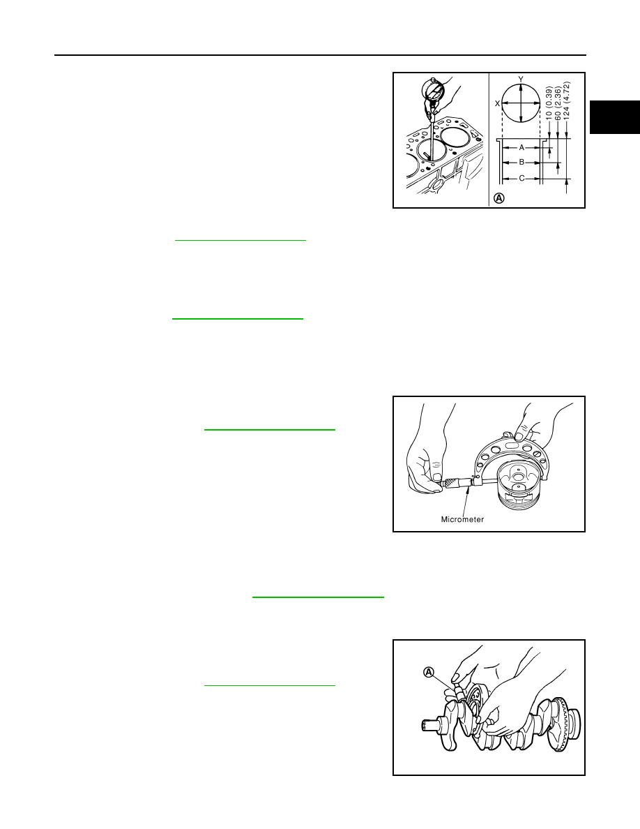
Cylinder Bore Inner Diameter
• Using a bore gauge, measure the cylinder bore for wear, out-of-
round and taper at six different points on each cylinder. (“X” and
“Y” directions at “A”, “B” and “C”) (“Y” is in longitudinal direction of
the engine)
NOTE:
When determining cylinder bore grade, measure cylinder bore at
“B” position.
• If the measured value exceeds the limit, or if there are scratches and/or seizure on the cylinder inner wall,
replace cylinder block.
NOTE:
There is no service setting for oversized piston.
Piston Skirt Diameter
Measure the outer diameter of piston skirt with a micrometer.
Piston to Cylinder Bore Clearance
Calculate by piston skirt diameter and cylinder bore inner diameter (direction “X”, position “B”).
(Clearance) = (Cylinder bore inner diameter) – (Piston skirt diameter)
• If it exceeds the limit, replace piston and piston pin assembly and/or cylinder block.
CRANKSHAFT MAIN JOURNAL DIAMETER
• Measure the outer diameter of crankshaft main journals with a
micrometer (A).
• If out of the standard, measure the main bearing oil clearance.
Then use undersize bearing. Refer to "MAIN BEARING OIL
CLEARANCE".
A
: Unit: mm (in)
Standard:
Cylinder bore inner diameter
: Refer to
.
Limit:
Out-of-round (Difference between“X”and“Y”)
Taper (Difference between“A”and“B”
: Refer to
.
PBIC3767E
Standard
: Refer to
.
PBIC0125E
Standard and Limit
: Refer to
Standard
: Refer to
.
PBIC3457J

EM-106
< DISASSEMBLY AND ASSEMBLY >
[HR16DE]
CYLINDER BLOCK
CRANKSHAFT PIN JOURNAL DIAMETER
• Measure the outer diameter of crankshaft pin journal with a micrometer.
• If out of the standard, measure the connecting rod bearing oil clearance. Then use undersize bearing. Refer
to "CONNECTING ROD BEARING OIL CLEARANCE".
OUT-OF-ROUND AND TAPER OF CRANKSHAFT
• Measure the dimensions at four different points as shown in the
figure on each main journal and pin journal with a micrometer.
• Out-of-round is indicated by the difference in dimensions between
“X” and “Y” at “A” and “B”.
• Taper is indicated by the difference in dimension between “A” and
“B” at “X” and “Y”.
• If the measured value exceeds the limit, correct or replace crankshaft.
• If corrected, measure the bearing oil clearance of the corrected main journal and/or pin journal. Then select
main bearing and/or connecting rod bearing. Refer to "MAIN BEARING OIL CLEARANCE" and/or "CON-
NECTING ROD BEARING OIL CLEARANCE".
CRANKSHAFT RUNOUT
• Place a V-block on a precise flat table to support the journals on
the both end of crankshaft.
• Place a dial indicator (A) straight up on the No. 3 journal.
• While rotating crankshaft, read the movement of the pointer on the
dial indicator. (Total indicator reading)
• If it exceeds the limit, replace crankshaft.
CONNECTING ROD BEARING OIL CLEARANCE
Method by Calculation
• Install connecting rod bearings to connecting rod and cap, and tighten connecting rod bolts to the specified
EM-94, "Disassembly and Assembly"
• Measure the inner diameter of connecting rod bearing with an
inside micrometer.
(Bearing oil clearance) = (Connecting rod bearing inner diameter)
– (Crankshaft pin journal diameter)
• If the clearance exceeds the limit, select proper connecting rod
bearing according to connecting rod big end diameter and crank-
shaft pin journal diameter to obtain the specified bearing oil clear-
ance. Refer to
EM-110, "Connecting Rod Bearing"
Method of Using Plastigage
• Remove engine oil and dust on crankshaft pin and the surfaces of each bearing completely.
• Cut a plastigage slightly shorter than the bearing width, and place it in crankshaft axial direction, avoiding oil
holes.
Standard
: Refer to
.
Limit:
Out-of-round (Difference between“X”and“Y”)
Taper (Difference between“A”and“B”)
: Refer to
.
PBIC3459J
Limit
: Refer to
PBIC3458J
Standard and Limit
: Refer to
EM-123, "Connecting Rod Bearing"
.
PBIC1642E

CYLINDER BLOCK
EM-107
< DISASSEMBLY AND ASSEMBLY >
[HR16DE]
C
D
E
F
G
H
I
J
K
L
M
A
EM
N
P
O
• Install connecting rod bearings to connecting rod and cap, and tighten connecting rod bolts to the specified
EM-94, "Disassembly and Assembly"
.
CAUTION:
Never rotate crankshaft.
• Remove connecting rod cap and bearing, and using the scale on
the plastigage bag, measure the plastigage width.
NOTE:
The procedure when the measured value exceeds the limit is
same as that described in the “Method by Calculation”.
MAIN BEARING OIL CLEARANCE
Method by Calculation
• Install main bearings to cylinder block and main bearing cap, and tighten main bearing cap bolts to the spec-
ified torque. Refer to
EM-94, "Disassembly and Assembly"
• Measure the inner diameter of main bearing with a bore gauge.
(Bearing oil clearance) = (Main bearing inner diameter) – (Crank-
shaft main journal diameter)
• If the clearance exceeds the limit, select proper main bearing
according to main bearing inner diameter and crankshaft main
journal diameter to obtain the specified bearing oil clearance.
Refer to
Method of Using Plastigage
• Remove engine oil and dust on crankshaft main journal and the surfaces of each bearing completely.
• Cut a plastigage slightly shorter than the bearing width, and place it in crankshaft axial direction, avoiding oil
holes.
• Install main bearings to cylinder block and main bearing cap, and tighten main bearing cap bolts to the spec-
ified torque. Refer to
EM-94, "Disassembly and Assembly"
CAUTION:
Never rotate crankshaft.
• Remove main bearing cap and bearings, and using the scale on
the plastigage bag, measure the plastigage width.
NOTE:
The procedure when the measured value exceeds the limit is
same as that described in the “Method by Calculation”.
MAIN BEARING CRUSH HEIGHT
PBIC1149E
Standard
: Refer to
.
PBIC1644E
PBIC1149E
Нет комментариевНе стесняйтесь поделиться с нами вашим ценным мнением.
Текст