Nissan Qashqai (2007-2010). Manual — part 38
EM-100
< DISASSEMBLY AND ASSEMBLY >
[HR16DE]
CYLINDER BLOCK
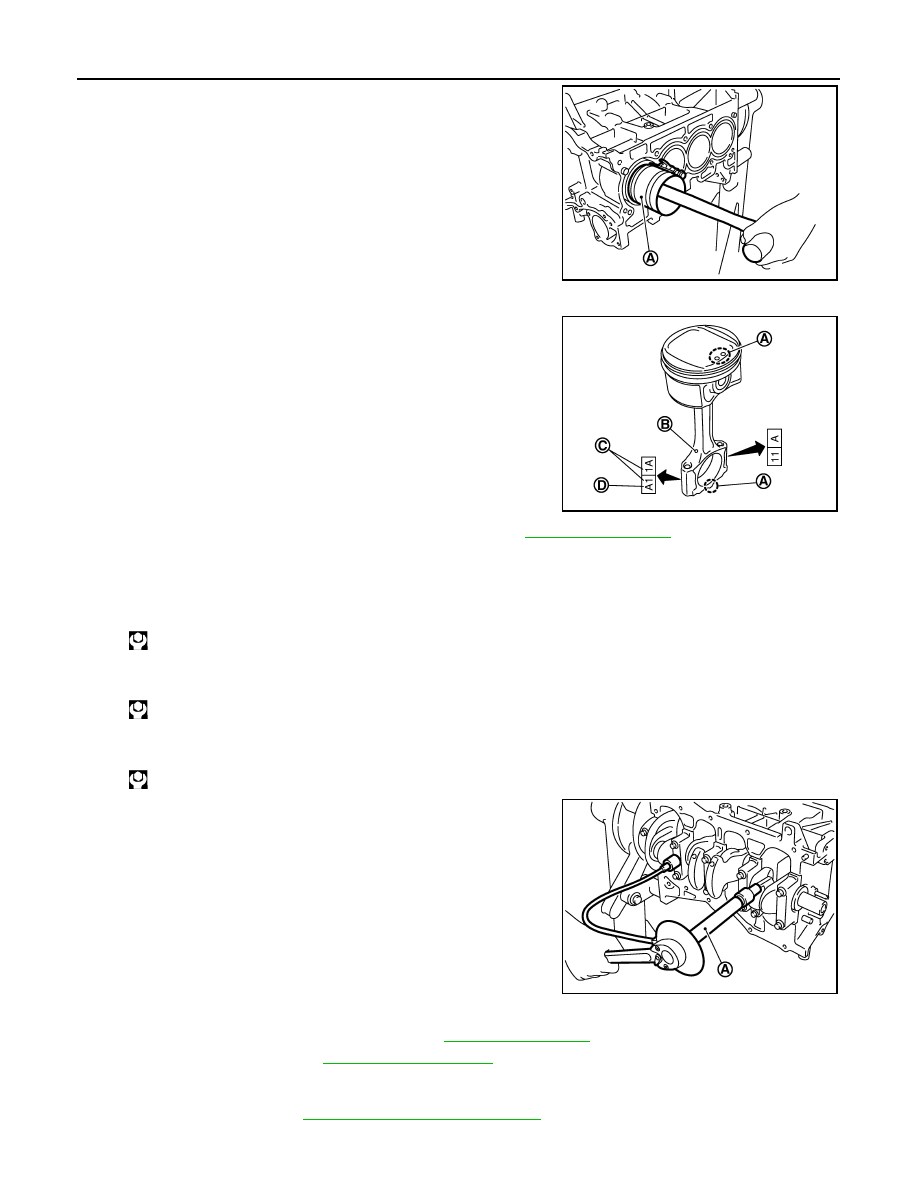
• Using the piston ring compressor (SST: EM03470000) (A) or
suitable tool, install piston with the front mark on the piston
head facing the front of the engine.
CAUTION:
• Be careful not to damage matching surface with con-
necting rod cap.
• Be careful not to damage the cylinder wall and crank-
shaft pin, resulting from an interference of the connect-
ing rod big end.
12. Install connecting rod cap.
• Match the stamped cylinder number marks (C) on connecting
rod with those on connecting rod cap to install.
13. Inspect outer diameter of connecting rod cap bolts. Refer to
.
14. Tighten connecting rod bolt with the following procedure:
a.
Apply new engine oil to the threads and seats of connecting rod bolts.
b.
Tighten bolts in several steps.
c.
Completely loosen bolts.
d.
Tighten bolts in several steps.
e.
Then turn all bolts 60 degrees clockwise (angle tightening).
CAUTION:
Confirm the tightening angle by using the angle wrench
[SST: KV10112100] (A) or protractor. Avoid judgment by
visual inspection without the tool.
• After tightening connecting rod bolt, make sure that crankshaft rotates smoothly.
• Check the connecting rod side clearance. Refer to
15. Install oil pan (upper). Refer to
NOTE:
Install the rear oil seal after installing the oil pan (upper).
16. Install rear oil seal. Refer to
EM-89, "Removal and Installation"
.
17. Install flywheel.
PBIC3765E
A
: Front mark
B
: Oil hole
D
: Connecting rod big end grade
JPBIA0537ZZ
: 27.5 N·m (2.8 kg-m, 20 ft-lb)
: 0 N·m (0 kg-m, 0 ft-lb)
: 19.6 N·m (2.0 kg-m, 14 ft-lb)
PBIC3753E
CYLINDER BLOCK
EM-101
< DISASSEMBLY AND ASSEMBLY >
[HR16DE]
C
D
E
F
G
H
I
J
K
L
M
A
EM
N
P
O
• Secure crankshaft with a stopper plate [SST: KV11105210], and tighten mounting bolts crosswise over
several times.
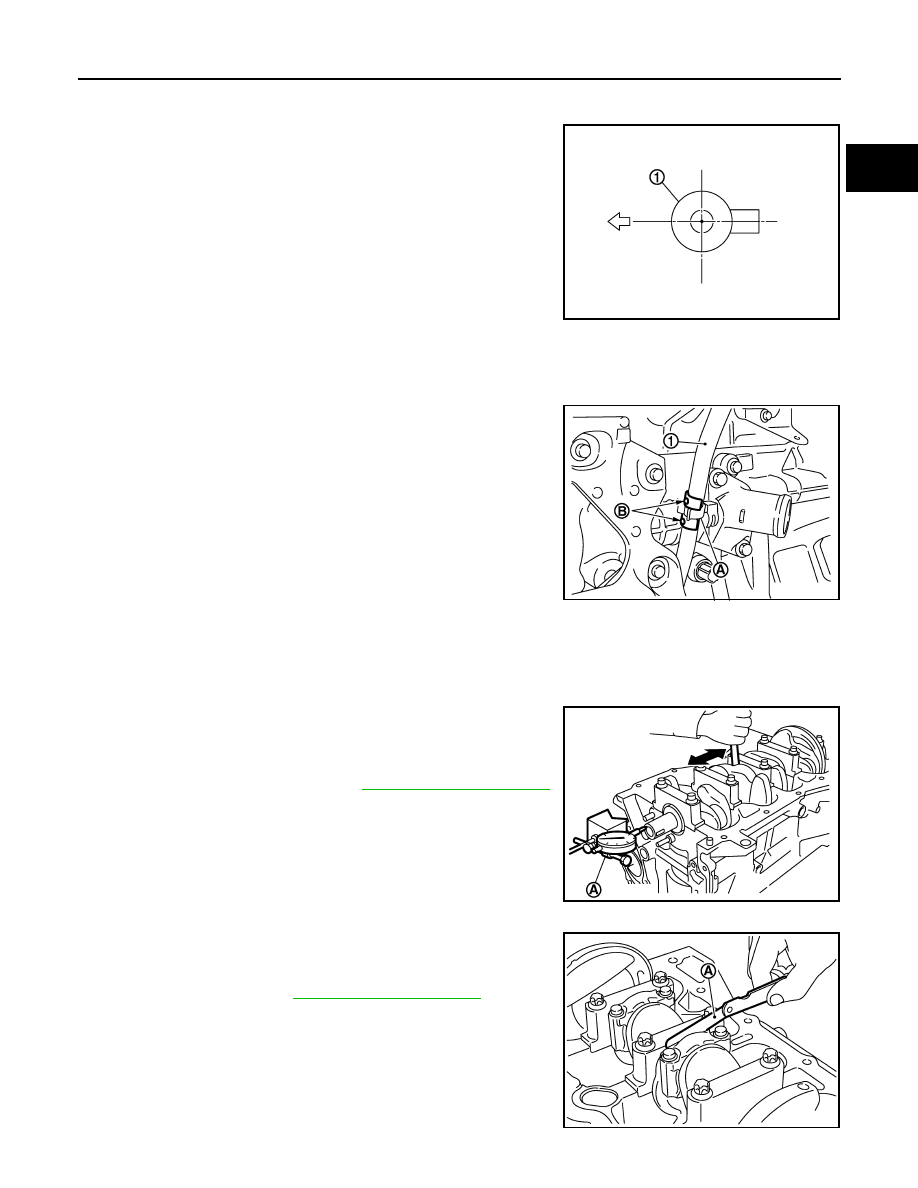
18. Install knock sensor (1).
• Install connectors so that they are positioned towards the rear
of the engine.
CAUTION:
• Never tighten mounting bolt while holding the connector.
• If any impact by dropping is applied to knock sensor,
replace it with a new one.
NOTE:
• Make sure that there is no foreign material on the cylinder
block mating surface and the back surface of knock sensor.
• Make sure that knock sensor does not interfere with other parts.
19. Install crankshaft position sensor (POS) and cover.
• Tighten bolts with it seated completely.
20. For the oil level gauge guide (1), fix the position (B) shown in the
figure to the water inlet clip (A) after inserting to the cylinder
block side.
21. Assemble in the reverse order of disassembly after this step.
Inspection
INFOID:0000000000893892
CRANKSHAFT END PLAY
• Measure the clearance between thrust bearings and crankshaft
arm when crankshaft is moved fully forward or backward with a dial
indicator (A).
• If the measured value exceeds the limit, replace thrust bearings,
and measure again. If it still exceeds the limit, replace crankshaft
also.
CONNECTING ROD SIDE CLEARANCE
• Measure the side clearance between connecting rod and crank-
shaft arm with a feeler gauge (A).
• If the measured value exceeds the limit, replace connecting rod,
and measure again. If it still exceeds the standard, replace crank-
shaft also.
: Engine front
PBIC3754E
PBIC3755E
Standard and Limit
: Refer to
.
PBIC3762E
Standard
: Refer to
.
PBIC3763E

EM-102
< DISASSEMBLY AND ASSEMBLY >
[HR16DE]
CYLINDER BLOCK
PISTON TO PISTON PIN OIL CLEARANCE
Piston Pin Hole Diameter
Measure the inner diameter of piston pin hole with an inside
micrometer.
Piston Pin Outer Diameter
Measure the outer diameter of piston pin with a micrometer.
Piston to Piston Pin Oil Clearance
(Piston to piston pin oil clearance) = (Piston pin hole diameter) – (Piston pin outer diameter)
• If oil clearance is out of the standard, replace piston and piston pin assembly.
PISTON RING SIDE CLEARANCE
• Measure the side clearance of piston ring and piston ring groove
with a feeler gauge.
• If the measured value exceeds the limit, replace piston ring, and
measure again. If it still exceeds the limit, replace piston also.
PISTON RING END GAP
• Make sure that cylinder bore inner diameter is within the specifica-
tion. Refer to "Cylinder Bore Inner Diameter".
• Lubricate with new engine oil to piston and piston ring, and then
insert piston ring until middle of cylinder with piston, and measure
piston ring end gap with a feeler gauge.
• If the measured value exceeds the limit, replace piston ring.
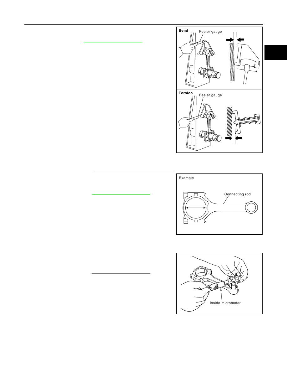
CONNECTING ROD BEND AND TORSION
Standard
: Refer to
PBIC0116E
Standard
PBIC0117E
Standard
Standard and Limit
: Refer to
.
SEM024AA
Standard and Limit
: Refer to
.
SEM822B
CYLINDER BLOCK
EM-103
< DISASSEMBLY AND ASSEMBLY >
[HR16DE]
C
D
E
F
G
H
I
J
K
L
M
A
EM
N
P
O
• Check with a connecting rod aligner.
• If it exceeds the limit, replace connecting rod assembly.
CONNECTING ROD BIG END DIAMETER
• Install connecting rod cap without connecting rod bearing installed, and tightening connecting rod bolts to
the specified torque. Refer to
EM-94, "Disassembly and Assembly"
• Measure the inner diameter of connecting rod big end with an
inside micrometer.
• If out of the standard, replace connecting rod assembly.
CONNECTING ROD SMALL END CLEARANCE
Connecting Rod Small End Inner Diameter
Measure the inner diameter of connecting rod small end with an
inside micrometer.
Piston Pin Outer Diameter
Limit
: Refer to
.
PBIC2077E
Standard
: Refer to
.
PBIC1641E
Standard
: Refer to
.
PBIC0120E
Нет комментариевНе стесняйтесь поделиться с нами вашим ценным мнением.
Текст