Nissan Qashqai (2007-2010). Manual — part 579
P0778 PRESSURE CONTROL SOLENOID B ELECTRICAL (SEC PRESSURE
SOLENOID VALVE)
TM-251
< COMPONENT DIAGNOSIS >
[CVT: RE0F10A]
C
E
F
G
H
I
J
K
L
M
A
B
TM
N
O
P
Is the inspection result normal?
YES
>> GO TO 3.
NO
>> Repair or replace damaged parts.
3.
CHECK HARNESS BETWEEN TCM AND PRESSURE CONTROL SOLENOID VALVE B (SECONDARY
PRESSURE SOLENOID VALVE)
1.
Turn ignition switch OFF.
2.
Disconnect TCM connector and CVT unit harness connector.
3.
Check continuity between TCM connector terminal and CVT unit harness connector terminal.
4.
If OK, check harness for short to ground and short to power.
5.
Reinstall any part removed.
Is the inspection result normal?
YES
>> GO TO 4.
NO
>> Repair or replace damaged parts.
4.
CHECK TCM
Check TCM input/output signals. Refer to
.
Is the inspection result normal?
YES
>> Check intermittent incident. Refer to
GI-39, "Intermittent Incident"
.
NO
Component Inspection
INFOID:0000000000988693
PRESSURE CONTROL SOLENOID VALVE B (SECONDARY PRESSURE SOLENOID VALVE)
1.
PRESSURE CONTROL SOLENOID VALVE B (SECONDARY PRESSURE SOLENOID VALVE)
1.
Turn ignition switch OFF.
2.
Disconnect CVT unit harness connector.
3.
Check resistance between CVT unit harness connector terminal and ground.
Is the inspection result normal?
YES
>> INSPECTION END
NO
>> Replace the transaxle assembly. Refer to
(2WD),
(4WD).
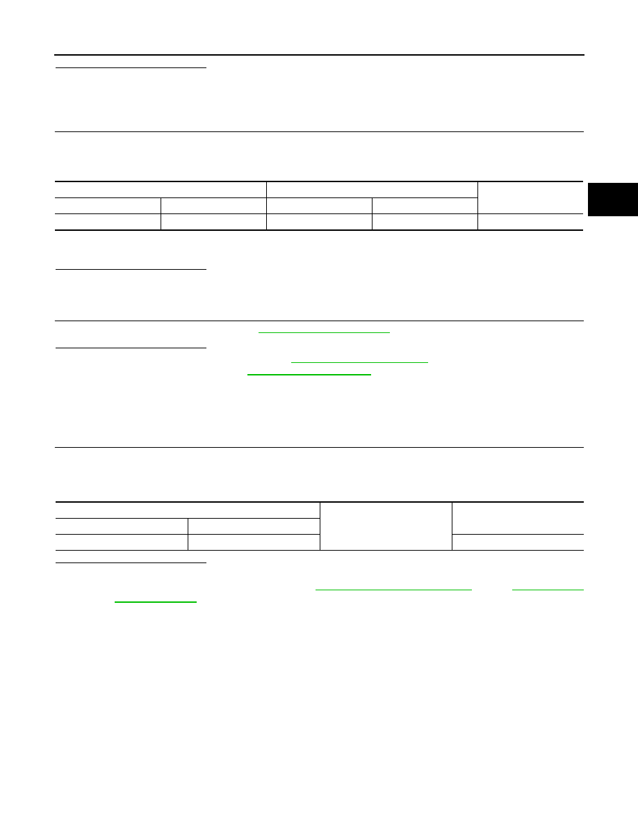
TCM connector
CVT unit harness connector
Continuity
Connector
Terminal
Connector
Terminal
F25
39
F24
3
Existed
CVT unit harness connector
Ground
Resistance (Approx.)
Connector
Terminal
F24
3
3.0 – 9.0
Ω

TM-252
< COMPONENT DIAGNOSIS >
[CVT: RE0F10A]
P0826 MANUAL MODE SWITCH
P0826 MANUAL MODE SWITCH
Description
INFOID:0000000000988694
Manual mode switch is installed in shift control device. The manual mode switch sends shift up and shift down
switch signals to TCM.
TCM sends the switch signals to combination meter via CAN communication line. Then manual mode switch
position is indicated on the shift position indicator.
DTC Logic
INFOID:0000000000988695
DTC DETECTION LOGIC
DTC CONFIRMATION PROCEDURE
CAUTION:
Always drive vehicle at a safe speed.
NOTE:
If “DTC CONFIRMATION PROCEDURE” has been previously conducted, always turn ignition switch
OFF and wait at least 10 seconds before conducting the next test.
After the repair, perform the following procedure to confirm the malfunction is eliminated.
1.
CHECK DTC DETECTION
With CONSULT-III
1.
Turn ignition switch ON.
2.
Select “DATA MONITOR”.
3.
Start engine.
4.
Drive vehicle for at least 2 consecutive seconds.
Is “P0826 MANUAL MODE SWITCH” detected?
YES
>> Go to
NO
>> Check intermittent incident. Refer to
GI-39, "Intermittent Incident"
.
Diagnosis Procedure
INFOID:0000000000988696
1.
CHECK MANUAL MODE SWITCH SIGNALS
With CONSULT-III
1.
Turn ignition switch ON.
2.
Select “DATA MONITOR”.
3.
Read out ON/OFF switching action of the “MMODE”, “NON M-MODE”, “UPLVR”, “DOWNLVR”.
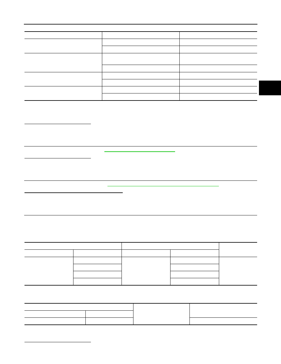
DTC
Item
(CONSULT-III screen term)
Malfunction is detected when...
Possible cause
P0826
MANUAL MODE SWITCH
When an impossible pattern of
switch signals is detected, a
malfunction is detected.
• Harness or connectors
- (These switches circuit is
open or shorted.)
- (TCM, and combination
meter circuit are open or
shorted.)
- (CAN communication line is
open or shorted.)
• Manual mode select switch
(Built into control device)
• Manual mode position select
switch (Built into control de-
vice)
MMODE
: ON
P0826 MANUAL MODE SWITCH
TM-253
< COMPONENT DIAGNOSIS >
[CVT: RE0F10A]
C
E
F
G
H
I
J
K
L
M
A
B
TM
N
O
P
Without CONSULT-III
Drive vehicle in the manual mode, and confirm that the actual gear position and the meter's indication of the
position mutually coincide when the selector lever is shifted to the “+ (up)” or “- (down)” side (1st
⇔
6th gear).
Is the inspection result normal?
YES
>> GO TO 5.
NO
>> GO TO 2.
2.
CHECK MANUAL MODE SWITCH
Check manual mode switch. Refer to
TM-254, "Component Inspection"
.
Is the inspection result normal?
YES
>> GO TO 3.
NO
>> Repair or replace damaged parts.
3.
CHECK SELF-DIAGNOSTIC RESULTS (COMBINATION METER)
Perform self-diagnosis check. Refer to
TM-216, "CONSULT-III Function (TRANSMISSION)"
Is any malfunction detected by self-diagnosis?
YES
>> Check the malfunctioning system.
NO
>> GO TO 4.
4.
CHECK MANUAL MODE SWITCH CIRCUIT
1.
Turn ignition switch OFF.
2.
Disconnect control device connector and combination meter connector.
3.
Check continuity between control device harness connector terminals and combination meter harness
connector terminals.
4.
Check continuity between control device harness connector terminal and ground.
5.
If OK, check harness for short to ground and short to power.
6.
Reinstall any part removed.
Is the inspection result normal?
YES
>> GO TO 5.
Item name
Condition
Display value
MMODE
Manual shift gate position (neutral)
ON
Other than the above
OFF
NONMMODE
Manual shift gate position (neutral, +side, -
side)
OFF
Other than the above
ON
UPLVR
Selector lever: + side
ON
Other than the above
OFF
DOWNLVR
Selector lever: - side
ON
Other than the above
OFF
Control device harness connector
Combination meter harness connector
Continuity
Connector
Terminal
Connector
Terminal
M57
7
M34
40
Existed
8
38
9
39
11
37
Control device harness connector
Ground
Continuity
Connector
Terminal
M57
10
Existed
TM-254
< COMPONENT DIAGNOSIS >
[CVT: RE0F10A]
P0826 MANUAL MODE SWITCH
NO
>> Repair open circuit or short to ground or short to power in harness or connectors.
5.
CHECK TCM
Check TCM input/output signals. Refer to
.
Is the inspection result normal?
YES
>> Check intermittent incident. Refer to
GI-39, "Intermittent Incident"
.
NO
Component Inspection
INFOID:0000000000988697
MANUAL MODE SWITCH
1.
MANUAL MODE SWITCH
Check continuity between control device harness connector terminals.
Is the inspection result normal?
YES
>> INSPECTION END
NO
>> Repair or replace damaged parts.
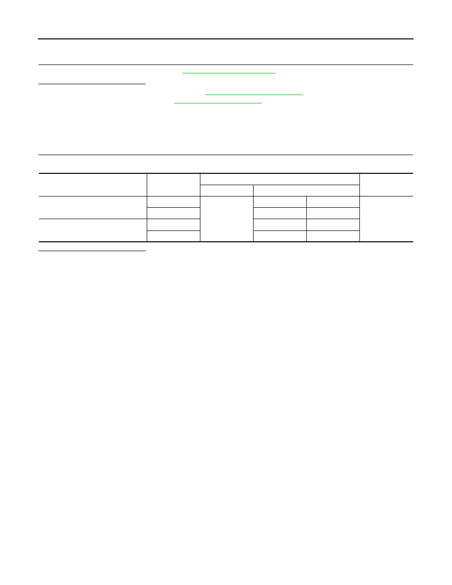
Item
Position
Control device harness connector
Continuity
Connector
Terminal
Manual mode select switch
Not manual
M57
10
11
Existed
Manual
7
10
Manual mode position select switch
Up
9
10
Down
8
10
Нет комментариевНе стесняйтесь поделиться с нами вашим ценным мнением.
Текст