Nissan Qashqai (2007-2010). Manual — part 666
FSU-1
SUSPENSION
C
D
F
G
H
I
J
K
L
M
SECTION
FSU
A
B
FSU
N
O
P
CONTENTS
FRONT SUSPENSION
SYMPTOM DIAGNOSIS . . . . . . . ...
NOISE, VIBRATION AND HARSHNESS
(NVH) TROUBLESHOOTING . . . . . . . .
NVH Troubleshooting Chart . . . . . . . . . ..
PRECAUTION . . . . . . . . . . . ...
PRECAUTIONS . . . . . . . . . . . . ...
Precaution Necessary for Steering Wheel Rota-
tion After Battery Disconnect . . . . . . . . .....
Precaution for Procedure without Cowl Top Cover
. ..
Precautions for Suspension . . . . . . . . . ..
PREPARATION . . . . . . . . . . .
PREPARATION . . . . . . . . . . . . ...
Special Service Tool . . . . . . . . . . . .....
Commercial Service Tool . . . . . . . . . . ..
ON-VEHICLE MAINTENANCE . . . . . .
FRONT SUSPENSION ASSEMBLY . . . . ...
Inspection . . . . . . . . . . . . . . . . ..
WHEEL ALIGNMENT . . . . . . . . . . ..
Wheel Alignment Inspection . . . . . . . . . ..
ON-VEHICLE REPAIR . . . . . . . . ..
FRONT COIL SPRING AND STRUT . . . . ..
Exploded View . . . . . . . . . . . . . . ..
Removal and Installation . . . . . . . . . . ..
Disassembly and Assembly . . . . . . . . . ..
Inspection . . . . . . . . . . . . . . . .
TRANSVERSE LINK . . . . . . . . . . .
Exploded View . . . . . . . . . . . . . . .
Removal and Installation . . . . . . . . . . .
Inspection . . . . . . . . . . . . . . . .
FRONT STABILIZER . . . . . . . . . .
Exploded View . . . . . . . . . . . . . . .
Removal and Installation . . . . . . . . . . .
Inspection . . . . . . . . . . . . . . . .
FRONT SUSPENSION MEMBER . . . . . .
Exploded View . . . . . . . . . . . . . . .
Removal and Installation . . . . . . . . . . .
Inspection . . . . . . . . . . . . . . . .
REMOVAL AND INSTALLATION . . . ...
FRONT SUSPENSION ASSEMBLY . . . . .
Exploded View . . . . . . . . . . . . . . .
Removal and Installation . . . . . . . . . . .
Inspection . . . . . . . . . . . . . . . .
SERVICE DATA AND SPECIFICATIONS
(SDS) . . . . . . . . . . . . . . .
SERVICE DATA AND SPECIFICATIONS
(SDS) . . . . . . . . . . . . . . . . .
Wheel Alignment . . . . . . . . . . . . . .
Ball Joint . . . . . . . . . . . . . . . . ..
FSU-2
< SYMPTOM DIAGNOSIS >
NOISE, VIBRATION AND HARSHNESS (NVH) TROUBLESHOOTING
SYMPTOM DIAGNOSIS
NOISE, VIBRATION AND HARSHNESS (NVH) TROUBLESHOOTING
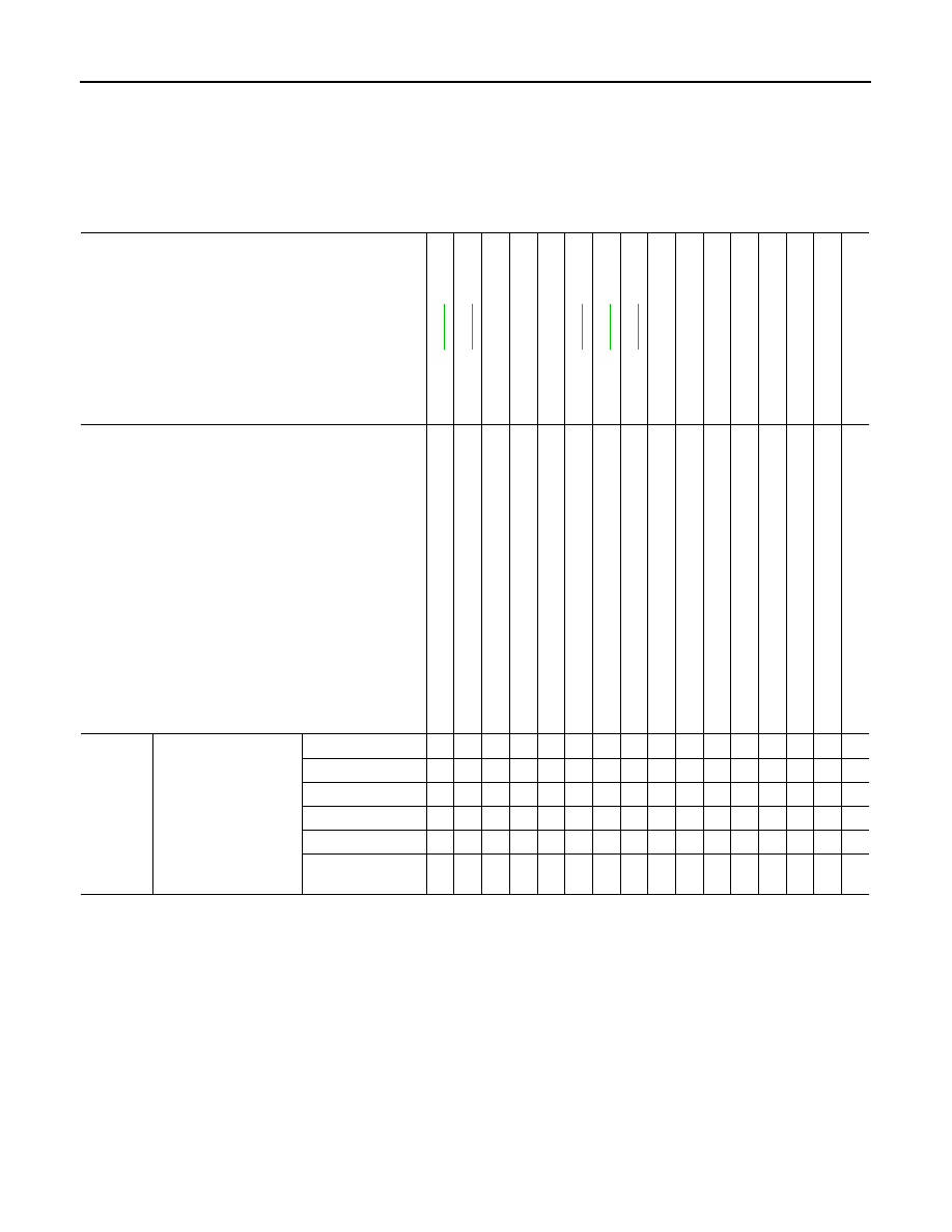
NVH Troubleshooting Chart
INFOID:0000000000970521
Use chart below to find the cause of the symptom. If necessary, repair or replace these parts.
×
: Applicable
Reference page
—
—
—
NVH in DLN
section
NVH in DLN
section
NVH in
F
AX
and FS
U sections
NVH in WT
section
NVH in WT
section
NVH in F
A
X section
NVH in BR
section
NVH in ST
section
Possible cause and SUSPECTED PARTS
Im
pro
p
e
r in
st
al
la
ti
on
,
lo
ose
n
e
ss
Sh
oc
k a
b
s
o
rb
er de
fo
rm
at
io
n
, d
a
m
a
g
e
or d
e
fl
ec
ti
o
n
B
u
s
h
in
g
or m
o
u
n
ti
ng
d
e
te
rio
rati
o
n
P
a
rt
s interference
S
p
ri
ng
fa
tig
u
e
S
u
s
p
e
n
s
ion
lo
os
en
es
s
In
co
rrec
t wh
ee
l a
lig
nm
en
t
S
ta
b
iliz
er b
a
r f
a
ti
gu
e
PR
OP
EL
LE
R
S
H
A
F
T (
4
W
D
)
DIFFERENTIAL (4WD)
F
R
ONT
AXLE AND FRONT S
U
SPENSION
TI
RE
S
ROAD
WHEELS
DRIV
E
SHAFT
BR
AK
E
S
S
T
EERING
Symptom
FRONT SUSPENSION
Noise
×
×
×
×
×
×
×
×
×
×
×
×
×
×
Shake
×
×
×
×
×
×
×
×
×
×
×
×
Vibration
×
×
×
×
×
×
×
×
×
×
Shimmy
×
×
×
×
×
×
×
×
×
×
Judder
×
×
×
×
×
×
×
×
Poor quality ride or
handling
×
×
×
×
×
×
×
×
×
×
PRECAUTIONS
FSU-3
< PRECAUTION >
C
D
F
G
H
I
J
K
L
M
A
B
FSU
N
O
P
PRECAUTION
PRECAUTIONS
Precaution for Supplemental Restraint System (SRS) "AIR BAG" and "SEAT BELT
PRE-TENSIONER"
INFOID:0000000000970522
The Supplemental Restraint System such as “AIR BAG” and “SEAT BELT PRE-TENSIONER”, used along
with a front seat belt, helps to reduce the risk or severity of injury to the driver and front passenger for certain
types of collision. This system includes seat belt switch inputs and dual stage front air bag modules. The SRS
system uses the seat belt switches to determine the front air bag deployment, and may only deploy one front
air bag, depending on the severity of a collision and whether the front occupants are belted or unbelted.
Information necessary to service the system safely is included in the SRC and SB section of this Service Man-
ual.
WARNING:
• To avoid rendering the SRS inoperative, which could increase the risk of personal injury or death in
the event of a collision which would result in air bag inflation, all maintenance must be performed by
an authorized NISSAN/INFINITI dealer.
• Improper maintenance, including incorrect removal and installation of the SRS, can lead to personal
injury caused by unintentional activation of the system. For removal of Spiral Cable and Air Bag
Module, see the SRC section.
• Do not use electrical test equipment on any circuit related to the SRS unless instructed to in this
Service Manual. SRS wiring harnesses can be identified by yellow and/or orange harnesses or har-
ness connectors.
Precaution Necessary for Steering Wheel Rotation After Battery Disconnect
INFOID:0000000001116344
NOTE:
• This Procedure is applied only to models with Intelligent Key system and NATS (NISSAN ANTI-THEFT SYS-
TEM).
• Remove and install all control units after disconnecting both battery cables with the ignition knob in the
″
LOCK
″
position.
• Always use CONSULT-III to perform self-diagnosis as a part of each function inspection after finishing work.
If DTC is detected, perform trouble diagnosis according to self-diagnostic results.
For models equipped with the Intelligent Key system and NATS, an electrically controlled steering lock mech-
anism is adopted on the key cylinder.
For this reason, if the battery is disconnected or if the battery is discharged, the steering wheel will lock and
steering wheel rotation will become impossible.
If steering wheel rotation is required when battery power is interrupted, follow the procedure below before
starting the repair operation.
OPERATION PROCEDURE
1.
Connect both battery cables.
NOTE:
Supply power using jumper cables if battery is discharged.
2.
Use the Intelligent Key or mechanical key to turn the ignition switch to the
″
ACC
″
position. At this time, the
steering lock will be released.
3.
Disconnect both battery cables. The steering lock will remain released and the steering wheel can be
rotated.
4.
Perform the necessary repair operation.
5.
When the repair work is completed, return the ignition switch to the
″
LOCK
″
position before connecting
the battery cables. (At this time, the steering lock mechanism will engage.)
6.
Perform a self-diagnosis check of all control units using CONSULT-III.
Precaution for Procedure without Cowl Top Cover
INFOID:0000000000970524

FSU-4
< PRECAUTION >
PRECAUTIONS
When performing the procedure after removing cowl top cover, cover
the lower end of windshield with urethane, etc.
Precautions for Suspension
INFOID:0000000000970525
CAUTION:
• When installing rubber bushings, the final tightening must be carried out under unladen conditions
with tires on ground. Oil might shorten the life of rubber bushings. Be sure to wipe off any spilled oil.
- Unladen conditions mean that fuel, engine coolant and lubricant are full. Spare tire, jack, hand tools
and mats are in designated positions.
• After servicing suspension parts, be sure to check wheel alignment.
• Self-lock nuts are not reusable. Always use new ones when installing. Since new self-lock nuts are
pre-oiled, tighten as they are.
PIIB3706J
Нет комментариевНе стесняйтесь поделиться с нами вашим ценным мнением.
Текст